 |
 |
| |
|
| 6AG7 Amplifier - Main Page and Exterior Photos | Tank Coil Construction Details |
| Interior Photos of the Finished Amplifier | Schematic Diagrams and Circuit Descriptions |
| Construction Photos | Testing And Preliminary Work |
| Typical Operating Conditions | Why Use A 6AG7? |
Making Your Own Coil Forms
The first problem in making a
tank coil is finding a
form and socket for the coil. Coil forms and sockets were previously made by
all of the big manufacturers (Millen, Miller, National, etc.) but that is not
the case today. If you are lucky enough to have some vintage coils forms and a
matching socket you are in business. But the solution for the rest of us is to
make our own forms and use a modern socket.
The most common socket that is big enough to be used for a tank coil is the
octal tube socket. These are readily available at hamfests and can be purchased
new from suppliers such as Antique
Electronic Supply. Octal tubes are still used in guitar amplifiers, and a
local amplifier repair shop might just have one in stock as well.
For the coil form you will need a 1" CPVC plumbing coupling and an 8-pin
plug. The 8-pin plug can be purchased at Antique Electronic Supply or at a
guitar shop or hamfest. The stock number at Antique Electronic Supply is
P-SP8-500. Get
several of these, as they are very handy. The CPVC coupling has an outer
diameter of 1 3/8", and is ideal for a coil form. Sand the 8-pin plug
down until it fits tightly into the coupling and you now have an excellent coil
form! See the photos below:
| Click here for a larger image. 1" CPVC Coupling and 8-Pin Plug |
Click here for a larger image. Completed Coil Form |
There is no need to glue the plug in if it fits snugly enough into the coupling. In fact, it is better that you don't glue it in because then it is easy to pull it back out should you decide to rewind the coil.
These coil forms are also great for use in a regenerative receiver. Below is a picture of a set of coils I wound for my Twinplex Regenerative Receiver using this type of coil form:
 Click here for a larger image. Coil Set for the AA8V Twinplex Regenerative Receiver |
Determining the Proper Number Of Turns
Now that we have a coil form for the tank coil, the problem comes down to two
questions:
"What size wire do I use?" and "How many turns of wire do I need
for each band?"
For a small amplifier like the 6AG7 Amplifier the answer to the first question
is easy: wire size is not that important. Any size larger than about #24 will
be big enough. The answer to the second question is more difficult.
There are formulas in the ARRL Handbook that can be used to determine the
proper inductance for a given design. There are also formulas that will tell
the coil dimensions (diameter, length, and number of turns) for a given
inductance. These can serve as a starting point, but in the end the best way to
determine the proper number of turns is by experiment.
This means you wind a few turns to start with, plug the coil in, and see if the
amplifier works. If it doesn't, you vary the number of turns until the
amplifier works the way you want. If you have a grid dip meter (or a unit like
the MFJ-259B
Antenna Analyzer with the
MFJ-66
grid dip attachment) you can plug in the coil and use the grid dip meter to see
if the coil resonates at the operating frequency. If it resonates at too low of
a frequency you will need to remove a few turns. If it resonates at too high a
frequency, you will need to add turns.
However, once you are in the ball park using the dip meter, I suggest that you
start with too many turns, plug in the coil, and test the power output from the
transmitter. Remove a turn or two, and retest. Do this until you get the
maximum output from the amplifier. Once you pass the maximum, simply rewind the
coil with the the number of turns that gave the most power out, and you're
done. It isn't as hard as it sounds, and it is probably the best way to
optimize the number of turns on the coil. This is exactly what I did with the
6AG7 amplifier.
Optimum Inductances for the 6AG7 Amplifier:
For the 6AG7 amplifier, I used the above method to determine the proper number
of turns for each band. I then used my
MFJ-259B
antenna analyzer to measure the inductance of each coil. The results are given
in the table below:
| Band | Inductance |
| 80m | 42.1 uH |
| 60m | 26.5 uH |
| 40m | 16.4 uH |
| 30m | 6.7 uH |
| 20m | 5.4 uH |
If you have an inductance meter or an antenna analyzer, such as the
MFJ-259B,
you can save a lot of time by simply winding your coils until they have the
inductances listed in the table above. Your coils should then be very close to
the optimum values. When measuring the inductances, be sure to keep your
connecting leads as short as possible., otherwise your readings will be
inaccurate!
My Plate Tank Coil Details:
Both of my coils for the 6AG7 amplifier are wound on National XR-5 five prong
coil forms. These forms have a diameter of 1 1/2 inches and are 2 1/4 inches
long. They require a 5 pin coil socket. I used band switching in my amplifier
because I only had two coil forms and I wanted to avoid having to switch coils
so often. I close wound my coils using #22 enameled magnet wire with a diameter
of 0.026" to 0.027". If you are lucky enough to have these coil forms
or another coil form with a diameter of 1 1/2 inches, and the correct size
wire, then you can easily duplicate my coils using the specifications below.
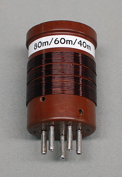
My 80m/60m/40m Tank Coil: My tank coil for the 80m/60m/40m bands consists of a 1 1/2" diameter National XR-5 five prong coil form close wound with #22 enameled magnet wire (diameter of about 0.026" to 0.027"). To strip enameled wire, burn it with a lighter or torch and then use 150 grit sandpaper to remove the ash down to the bare copper. Choose which pins of the coil will be connected to the 625 pf loading capacitor and the A, B, and C positions of the bandswitch (I don't currently use position D). You will need to keep these in mind as you follow the instructions below. In my amplifier, position "A" of the bandswitch corresponds to 80m/30m, position "B" corresponds to 60m/20m, and position "C" corresponds to 40m. To wind the coil, drill a 1/16" hole about 1/2" from the bottom of the coil form. Strip one end of the enameled wire, run it through the hole, and solder it to the coil form pin that you have decided will be connected to the 625 pf loading capacitor. Keeping the wire as tight as practical, wind up exactly 15 turns. Drill a hole at the end of the winding, pass the wire through, and, after stripping it, connect the wire to the pin on the coil that will be connected to the 40m position of the band switch (position C). We will call this pin on the coil form pin "C". Do not solder to this pin yet! These 15 turns are the 40m winding. Now run another stripped wire through this same hole, and connect it to pin "C" as well. Solder these two wires to the pin. Now tightly wind up exactly nine turns, drill another hole at the end of the winding, strip the wire, and run this through the hole to the pin on the coil form that will be connected to the 60m/20m position of the band switch (position B). We will call this pin on the coil form pin "B". As before, do not solder this lead yet. These 9 turns, plus the previous 15 turns (for a total of 24 turns), are the 60m winding. Now run another stripped wire through this same hole, and connect it to pin "B" as well. Solder these two wires to the pin. Now wind up exactly nine more turns, drill another hole at the end of the winding, strip the wire, and run this through to the pin on the coil form that will be connected to the 80m/30m position of the band switch (position A). We will call this pin of the coil form pin "A". Solder the wire to the pin. These 9 turns, plus the other 24 turns (for a total of 33 turns), are the 80m winding. In summary, the 80m winding consists of a total of 33 turns, the 60m winding consists of a total of 24 turns, and the 40m winding consists of 15 turns. |
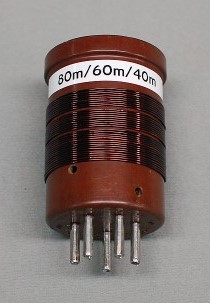
Click on the image for a larger view. Click here for a super detailed view. |
My 30m/20m Tank Coil: The tank coil for the 30m/20m bands is made the same way, except that it only has two smaller windings. It is close wound on a National XR-5 five prong coil with #22 enameled magnet wire. To wind the coil, drill a 1/16" hole about 1/2" from the bottom of the coil form. Strip one end of the enameled wire, run it through the hole, and solder it to the coil form pin that you have decided will be connected to the 625 pf loading capacitor. Keeping the wire as tight as practical, wind up exactly 7 turns. Drill a hole at the end of the winding, pass the wire through, and, after stripping it, connect the wire to the pin on the coil that will be connected to the 60m/20m position of the band switch (position B). We will call this pin on the coil form pin "B". Do not solder to this pin yet! These 7 turns are the 20m winding. Now run another stripped wire through this same hole, and connect it to pin "B" as well. Solder these two wires to the pin. Now tightly wind up exactly 3 turns, drill another hole at the end of the winding, strip the wire, and run this through the hole to the pin on the coil form that will be connected to the 80m/30m position of the band switch (position A). We will call this pin on the coil form pin "A". Solder this lead to the pin. These 3 turns, plus the previous 7 turns (for a total of 10 turns), are the 30m winding. In summary, the 30m winding consists of a total of 10 turns, and the 20m winding consists of a total of 7 turns. |
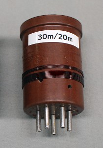
Click on the image for a larger view. Click here for a super detailed view. |
 Back to Dr. Greg Latta's
Electrical Engineering and Amateur Radio Pages
Back to Dr. Greg Latta's
Electrical Engineering and Amateur Radio Pages
 If you have any questions or
comments, you can send E-Mail to Dr. Greg Latta at
glatta@frostburg.edu
If you have any questions or
comments, you can send E-Mail to Dr. Greg Latta at
glatta@frostburg.edu