
Click on the image for a larger view.
Click here for a super detailed view.
A Brand New JAN (Joint Army Navy) 6AG7 Vacuum Tube
Introduction:
One question that I am often asked is "How do you know which tube to use
in your circuit?" It's not an easy question to answer, but on this page I
will walk you through how I came to choose the 6AG7 tube for this amplifier. By
following along with me on this example you should get a general idea of how to
choose a tube for a particular application.
Sources of Tube Data and Information:
To begin with we need to have tube reference information. The information can
take the form of books, tube data sheets, magazine articles, and
advertisements. Some of this information is available on the web, and some of
it is available in print. Two books that I highly recommend were originally
published by RCA. They are the RCA RC-30 Receiving Tube Manual and the RCA TT-5
Transmitting Tube Manual. The covers of these two books are shown below:
 RCA RC-30 Receiving Tube Manual |

RCA TT-5 Transmitting Tube Manual |
These two books cover just about everything we might want to know about
vacuum tubes. Besides data sheets on individual tubes, they also contain
chapters on the theory of vacuum tubes, the care and feeding of vacuum tubes,
suggested circuits, and application guidelines. The application guidelines are
particularly helpful in finding a tube for a specific application. Both of
these books are still in print and can be obtained from either
RF Parts or
Antique Electronic Supply. No
library is complete without them.
On-line, Frank's Electron Tube Pages
are a tremendous resource. (Thanks Frank!) Frank's Electron Tube Pages contain
multiple data sheets for virtually every tube that is out there. The site does
not contain application tables, but once you have a particular tube in mind you
will be able to get many different data sheets on that tube.
Finally, another great source of tube information, particularly on amateur
radio applications, is the back of earlier ARRL handbooks and back issues of
QST magazine. The ARRL handbooks contain
abbreviated tables of tube data and tube base diagrams that are extremely
useful, as well as many construction projects that use vacuum tubes. The
handbooks also have excellent chapters on the theory of how tubes work. Back
issues of QST magazine from the 1930s up to the 1970s are full of classic
construction projects using tubes, articles on tubes and tube theory, and
advertisements by tube manufacturers that often contain tables recommending
specific tubes for specific applications. If you are an
ARRL member, you can access back issues of
QST on-line. Otherwise, they are available on CD-ROM or at the library. I
personally think that the digital on-line QST data base is by itself worth the
price of an ARRL membership.
Let's see now how we can put this information to use.
Decide On The Application - i.e. What You Want The
Tube To Do:
For the information to be useful we must first answer the question:
"What exactly do we want the tube to do?" In our case, we want
an RF amplifier that can take the output of an amplified
N3ZI digital VFO and raise it to the
point where it will drive a 6146B. This means we must find out how much power
is needed by the 6146B and how much power is provided by the amplified
N3ZI digital VFO.
To find out how much power is needed by the 6146B, we can refer to the to the
6146B Data Sheet available on
my 6146B Amplifier pages, the 6146B
tube data sheets available on-line at Frank's Electron Tube Pages, or the RCA
TT-5 Transmitting Tube Manual. According to the data sheets, a single 6146B
operating in class AB2 (i.e. drawing grid current) requires about 0.1 watts to
0.25 watts of drive. Doubling this to account for circuit losses means that we
will need at least 0.5 watts (1/2 watt) to reliably drive a 6146B. If we also
want to use the amplifier by itself as a QRP transmitter, more output, say at
least 2 watts, is desirable.
To find out out how much power we have available to drive our amplifier, we
use an oscilloscope to measure the output the N3ZI digital VFO. This was
found to be a maximum of about about 5 volts peak to peak across 50 ohms up to
7 MHz, with less output at higher frequencies. 5 volts peak to peak works out
to 1.77 volts RMS. Across 50 ohms that means we have 0.0625 watts (62.5 mw) to
work with! This isn't much, but it will have to do.
Going from 0.0625 watts to 2 watts is a power gain of 15 db. This is definitely
possible in a single tube stage, provided that the proper tube is used.
Searching Through QST Magazine Was The Easiest Way
To Find A Tube:
Though I could have used the application tables in the RC-30 Receiving Tube
Manual, I remembered in my many leisurely readings of back issues of QST
magazine (on CD-ROM) that I had seen advertisements from RCA that recommended
specific tubes for specific amateur radio applications. After hunting
through my CD-ROM collection of QST I found the following two advertisements
from QST Magazine in the 1948 and 1952 issues:
 Click For A Larger Image From QST Magazine, November, 1948, Page 146 |
 Click For A Larger Image From QST Magazine, November, 1952, Page 138 |
You can click on the images for a close-up view of the advertisements. The left advertisement is from the November 1948 issue of QST, page 146. It lists a variety of receiving tubes and their maximum ratings for use in amateur radio service. These are noticeably higher than their ratings for receiving service as listed in the RCA RC-30 Receiving Tube Manual. The right advertisement, from the November 1952 issue of QST, page 138, lists a variety of applications and the tubes recommended for them by RCA. Notice that six tubes are recommended for use as a buffer (i.e. driver), which is exactly the application we are considering here. Let's take a look at these six tubes, plus three others with similar characteristics that were introduced after 1952: the 12BY7A, the 6CL6, and the 6AQ5A. In the table below are listed the mutual conductances and plate dissipations of these 9 tubes as obtained from the RCA tube manual or on-line at Frank's Electron Tube Pages:
| Tube | Mutual Conductance (Transconductance ) |
Plate Dissipation | Base Type: |
| 6AG7 | 11,000 micromhos | 9 watts | metal octal |
| 6AK6 | 2300 micromhos | 2.75 watts | 7-pin miniature |
| 6AQ5A | 3700 micromhos | 12 watts | 7-pin miniature |
| 6CL6 | 11,000 micromhos | 7.5 watts | 9-pin miniature |
| 6F6 | 2600 micromhos | 11 watts | metal octal |
| 6J6 | 5300 micromhos | 1.5 watts | 7-pin miniature |
| 6L6GC | 5200 micromhos | 30 watts | glass octal |
| 6V6GTA | 3700 micromhos | 14 watts | glass octal |
| 12BY7A | 11,000 micromhos | 6.5 watts | 9-pin miniature |
Before we go on, let's discuss exactly what we mean by "Mutual Conductance" and "Plate Dissipation":
Mutual Conductance Is A Measure Of The
Actual Gain Of A Tube:
In the table above the second column is labeled "Mutual Conductance".
The mutual conductance is the best measure of a tube's ability to actually
amplify a signal. (Not the amplification factor as is often thought!)
What we really do in a tube is to vary the grid voltage to cause a
corresponding variation in plate current. The higher the change in plate
current for a given change in grid voltage, the higher the actual gain (mutual
conductance) of the tube. If we change the grid voltage on a tube by a specific
amount, and measure the associated change in plate current, then the change in
plate current divided by the associated change in grid voltage is defined as
the mutual conductance or transconductance of the tube. For
instance, if the plate current changes by 4 mA when the grid voltage is changed
by 2 Volts, the mutual conductance is 4 mA/2 Volts or 2 mA/V. Now, 1A/1V is the
unit of conductance and is defined as a reciprocal ohm or "mho",
since ohm spelled backwards is "mho". Thus 2mA/V is equal to 2
millimhos. It is customary to list mutual conductances in micromhos, where 1
millimho=1000 micromhos. Thus, in this example the the mutual conductance would
be 2000 micromhos or 2000 umho.
Plate Dissipation Is A Measure Of The Tube Plate's
Ability To Safely Dissipate Heat:
The third column lists the plate dissipation. In operation, the electrons
striking the plate of the tube produce heat, which must be eliminated by
radiation or conduction from the tube. The plate dissipation is the maximum
amount of heat that can be safely dissipated by the plate of the tube on a
continuous basis. Tubes with larger plate dissipations are usually larger and
more expensive.
Cutting Down The Number Of Tube Choices To A Single
Tube:
Now, returning to our amplifier, the small amount of drive available from the
VFO means that a voltage (class A) amplifier will have to be used. Class A
amplifiers are very linear and the grid current in a properly operating class A
amplifier is zero. This means that a class A amplifier has a relatively
high input impedance and does not theoretically require any driving
power.. (Class B and C amplifiers usually draw grid current and do
require driving power.) Since we want as much gain as possible, we want the
the mutual conductance of the tube to be as large as possible. The table
above shows that three tubes stand out with the highest mutual conductance: the
6AG7, 6CL6, and 12BY7, all with a mutual conductance of 11,000 micromhos.
Now, the mutual conductance is not absolutely constant, but changes with the
bias applied to the tube. In general, the mutual conductance increases as the
bias on the tube is decreased. However, decreasing the bias in a class A
amplifier increases the plate dissipation. Thus, all other things being
equal, we want the highest plate dissipation possible. That leaves us with the
6AG7. A final check in the RCA Receiving Tube manual shows that a 6AG7
operating as a class A amplifier is able to put out 3 watts of power. This is
exactly what we are looking for!
RCA's Conclusion Is The Same As Mine:
It is truly dumb luck that the prototype
transmitter that I decided to modify for testing purposes was already based
on a 6AG7 tube! After optimizing the
RF tank coils, I found that I could get slightly more than 3 watts out of
the amplifier, exactly as predicted by the RCA Receiving Tube Manual. I later
found the following advertisement in the April 1952 issue of QST magazine, page
146:
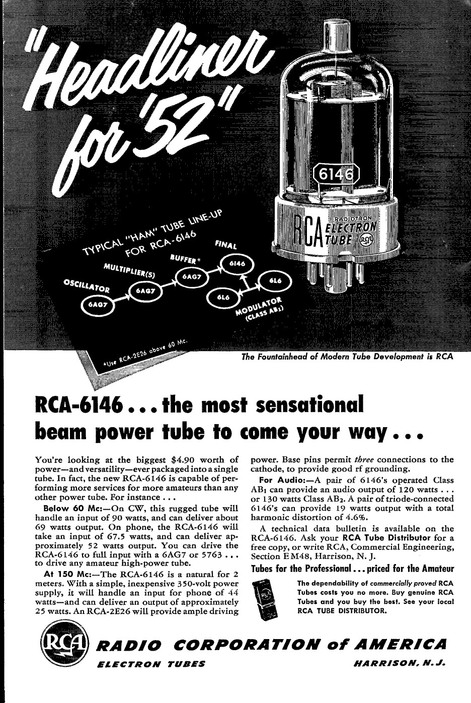
Click For A Larger Image
April, 1952 Issue of QST Magazine, Page 146
The advertisement clearly indicates RCA's choice of a 6AG7 to drive the 6146. It is heartening to know that RCA and I are in agreement!
Final Comments:
In summary, when choosing a tube for a specific application, you must first
have access to the tube data. Then you must decide on the specific
application and requirements. You can then consult the data to narrow
down your choice. In the end, you may find several tubes that will do the
job. For instance, the 6CL6 is actually the 9-pin version of the 6AG7. My guess
is that, with a slight change in the tube bias to decrease the plate
dissipation, the 6CL6 would also work fine, with slightly less output. It might
also come down to using what you have on hand. Though another tube might look
better on paper, if money is tight and you have a particular one on hand, then
that tube may be the one to use. The answer isn't always cut and dyed.
Epilogue:
Since I had spent so much time searching through back issues of QST magazine, I
kept searching to see what else I might stumble onto concerning the 6AG7 and
metal tubes in general. As luck would have it I also found the following two
advertisements:
 Click For A Larger Image From QST Magazine, December, 1949, Page 1 |
 Click For A Larger Image From QST Magazine, September, 1935, Page 61 |
The left ad is an advertisement put out by KenRad Radio Tubes for their 6AG7, listing it as their tube of choice for service as a VFO (variable frequency oscillator). This is the tube that is used in the VFO of the Wingfoot VFO Exciter. Also, in 1950, an important article in QST magazine, "Crystal-Controlled Oscillators, A Review of Modern Crystals, Circuits and Tubes" (QST, March 1950, C. Vernon Chambers, W1JEQ) looked at various electron-coupled circuits and a variety of tubes: the 6AG7, 6F6, 6V6GT, and 6L6. Among the many conclusions in the article, one came through loud and clear, which I quote here: "Of the four tubes tested the 6AG7 is by far the best from every standpoint." As a result of that article, virtually all crystal oscillator circuits in the ARRL handbook for the next 15 years featured or recommended the use of the 6AG7.
The advertisement on the right is from the September 1935 issue of QST magazine. Here, General Electric is for the first time advertising their latest receiver using the "New All-Metal Tubes". The metal tube concept was really just a marketing ploy to try to capture more of the market, since you could get the same shielding effect by just putting a metal shield over a glass tube. Nonetheless, the all-metal tubes were here to stay and arrived just in time for WW2, where a metal case was a distinct advantage, since it didn't break if dropped! After the war, however, most metal tubes were released in glass varieties . Examples are the 6V6GT for the 6V6, the 6L6GC for the 6L6, and the 6CL6 for the 6AG7. The glass tubes were just as good and cheaper to manufacture, and the metal tubes eventually fell into disuse, ending an important chapter in the history of vacuum tubes.
 Back to Dr. Greg Latta's
Electrical Engineering and Amateur Radio Pages
Back to Dr. Greg Latta's
Electrical Engineering and Amateur Radio Pages
 If you have any questions or
comments, you can send E-Mail to Dr. Greg Latta at
glatta@frostburg.edu
If you have any questions or
comments, you can send E-Mail to Dr. Greg Latta at
glatta@frostburg.edu