| 6AG7 Amplifier - Main Page and Exterior Photos | Tank Coil Construction Details |
| Interior Photos of the Finished Amplifier | Schematic Diagrams and Circuit Descriptions |
| Construction Photos | Testing And Preliminary Work |
| Typical Operating Conditions | Why Use A 6AG7? |
After I decided to build a VFO amplifier, I remembered that years ago a
friend of mine, Jim Trutko, W8EXI, I had given me a one tube crystal oscillator
transmitter that used a 6AG7 tube. Jim gave me the transmitter, along with the
Wingfoot VFO Exciter, when
he decided to move out of his house and into a retirement community. I had
stored the transmitter in a corner of my shop, and when I retrieved it I was
delighted to find that it contained most of the parts I would need to build an
amplifier, and the power transformer and power choke were in good condition. It
was absolutely filthy and grimy (it was in Jim's garage a long time!) and it
would need some serious work to clean it up, but otherwise it would do the job.
The chassis turned out to be quite flimsy, and was badly rusted. Rather than
try to strengthen it, clean it up, and paint it, I decided it would be better
to rebuild the entire amplifier on a new, stronger, chassis after I had
thoroughly tested and debugged it. Since I would eventually be tearing the
entire thing apart, I didn't worry about proper wire dress and soldering
techniques. The idea was to get it jury rigged together only for testing
purposes.
The original transmitter used a link coupled output, which was fine for the
balanced transmission lines used back in the 1950s and 1960s, but it was not
well suited for use with coaxial cable. It was also rather inflexible, as it
was hard to vary the number of turns on the link coupling. A pi-network output
would be much better, and this meant that I needed to add a loading capacitor
to the circuit. After testing several variable capacitors from my junk box, I
selected a 625 pf unit and mounted it onto the chassis with a single
screw. This was sufficient for testing purposes. The capacitor had a dial cord
drum on the front that served well as a knob. It was later removed and
replaced.
Testing showed that the two original coils were for 80m and 20m. I also had a
set of coils from an Ameco AC-1 transmitter and I found that these also worked
with the amplifier, but none of the coils (including the original coils)
would deliver the output that I expected, which was around 3 watts. Typically I
was only getting about 1 watt out of the amplifier, more than enough to drive
the 6146B amplifier, but barely enough
to make QRP contacts when using the amplifier on its own.
Since the the N3ZI VFO I was using
could operate on any frequency up to 34 MHz, I tried using the coils on
frequencies other than those for which they were originally intended. For
example, I found that if I used the original 80m coil at 5.5 MHz, rather than
3.5 MHz, I could get 3 watts out rather than 1 watt. According to the RCA tube
manual, 3 watts was all that could be expected from the 6AG7 when operated as a
class A amplifier, so this was the best I could expect. However, it indicated
that all of the coils would need more inductance, i.e. more turns. Eventually,
after rebuilding the
amplifier on a new chassis, I optimized the coils for all five
bands and got much more output.
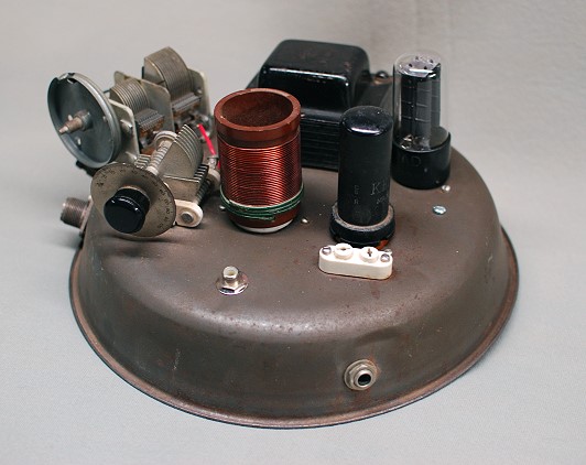
Top View: This is a top view of the 6AG7 transmitter after it has been modified and turned into an amplifier. Though the amplifier is fully functional at this point, it sure isn't pretty. The 625 pf loading capacitor is in the back on the left, and has been jury rigged into place. It is barely held in place by one screw. The white crystal socket at the right is no longer used, and an RCA jack has been added at the top in the front to function as an input jack. The coil in the photo is the original 80m coil, and it still contains the original green link coupling, though the link coupling is not being used. The power transformer in the back has not yet been restored, and is quite rusty. |
Click on the image for a larger view. Click here for a super detailed view. |
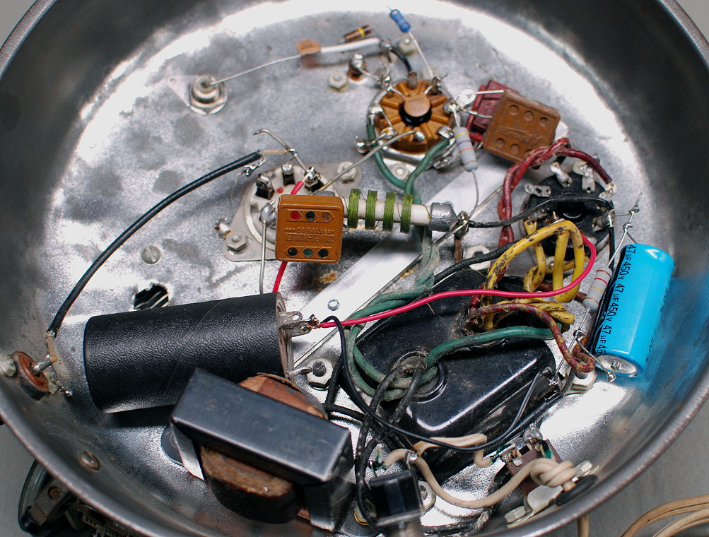
| Bottom View: What a mess! Believe it or not, this actually works. While testing the amplifier I did not pay much attention to lead dress or proper soldering techniques. The goal was to simply get the thing working and to work out the bugs in the design. The large black capacitor is a very old junk box capacitor I used in the power supply to get the power supply working. It had a voltage rating lower than I would have liked, but it held up. The transformer wiring was very filthy, and part of the transformer restoration involved carefully removing all of the grime from the transformer leads. In this photo the white socket near the center is the coil socket, the burnt-orange octal socket is the 6AG7 socket, and the black octal socket is the 5Y3 socket. The power supply filter choke is slightly to the left at the bottom of the photo. |
 Click on the image for a larger view. Click here for a super detailed view. |
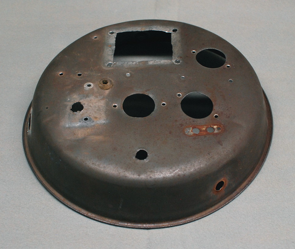
| Cake Pan Without Parts: After the amplifier was breadboarded and tested all of the parts were removed to be rebuilt on a new chassis. This is what the original chassis looked like when all of the parts were removed. What exactly it was originally is hard to tell. It could have been a cake pan, or perhaps a reflector for a light fixture. It is hard to say. Regardless, it was rusty and flimsy, so I decided to rebuild the amplifier on a new chassis. However, in keeping with the original idea, I decided to use a square cake pan as the new chassis. |
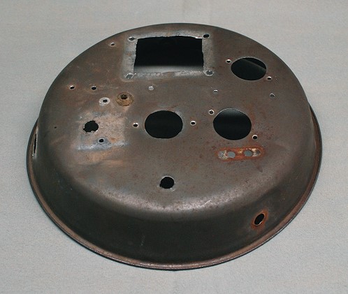 Click on the image for a larger view. Click here for a super detailed view. |
 Back to Dr. Greg Latta's
Electrical Engineering and Amateur Radio Pages
Back to Dr. Greg Latta's
Electrical Engineering and Amateur Radio Pages
 If you have any questions or
comments, you can send E-Mail to Dr. Greg Latta at
glatta@frostburg.edu
If you have any questions or
comments, you can send E-Mail to Dr. Greg Latta at
glatta@frostburg.edu