Click on the image for a larger view.
Click here for a super detailed view.
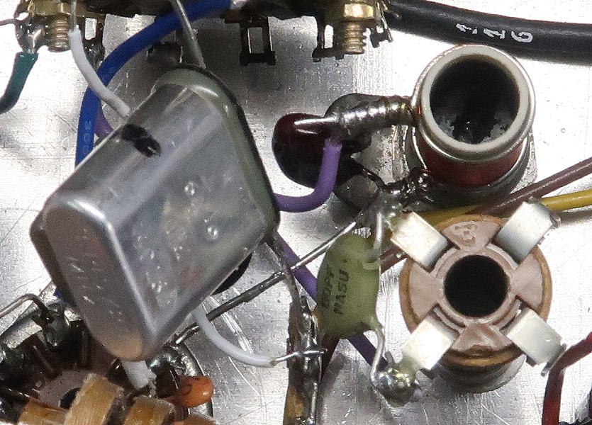
| 6x2C Crystal Controlled Converter - Main Page and Exterior Photos | Interior Photos |
| How To Operate The 6x2C Converter | Alignment and Voltage Table |
| Schematic Diagram and Circuit Descriptions | Mechanical Construction |
| Parts and Construction | Choosing Crystal Frequencies |
| Alignment |
| Operating Voltage Tables |
| Current Calculations |
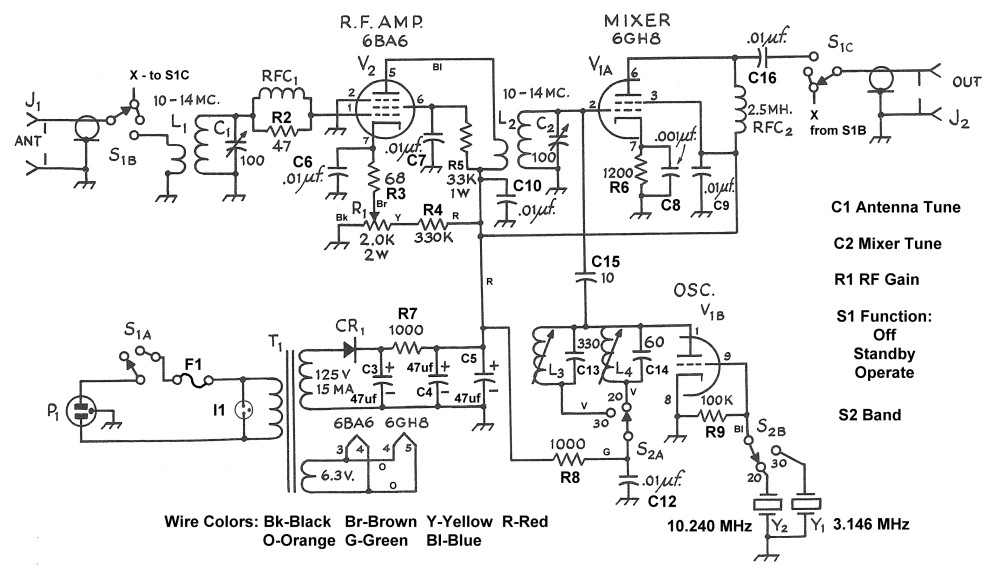
| Schematic Diagram |
Alignment:
The only alignment required is the adjustment of oscillator coils L3 and L4. If
an RF probe is available, measure the RF voltage at pin 1 of V1. Adjust the
appropriate coil for a maximum. Then move the slug away from the maximum one
way and then the other. One way the reading will drop off more slowly. Go back
to the maximum, and then turn the slug in the direction where the reading drops
off more slowly about 1 or 2 turns. If you don't have an RF probe, use a pickup
loop with an oscilloscope to observe the output. Note: Do not tune for maximum
output. You want the coil slightly away from the maximum on the side where the
output drops off more slowly. (In my 6x2C I have the slugs all the way out.)
Operating Voltage
Tables:
The tables below represent the typical operating voltages present at various
points in the 6x2C converter. These measurements are valid for this
particular converter only and are valid only under the conditions
indicated.
Operating Voltage
Tables
| Function | Tube Designator |
Tube Type |
Pin 1 | Pin 2 | Pin 3 | Pin 4 | Pin 5 | Pin 6 | Pin 7 | Pin 8 | Pin 9 |
| Mixer/ Crystal Oscillator |
V1 | 6GH8A | Do Not Measure* |
0 | 122V | ** | 6.06V AC (Between pins 4 and 5)** |
122V | 4.00V | 0 | Do Not Measure* |
| RF Amplifier | V2 | 6BA6 | 0V | 0V | ** | 6.06V AC (Between pins 3 and 4)** |
122V | 60V | 0.45V | - | - |
| Location | Measurement |
| Junction of CR1, C3, and R7 | 137V |
| Junction of R7, C4, C5 | 122V |
| Junction of R8 and C12 | 118V |
Measurement Conditions:
All measurements were taken at a line voltage of 123V AC.
All measurements were taken with the RF Gain control all the way up.
All measurements are in DC volts unless otherwise indicated.
All measurements were taken with an 11 Mohm input voltmeter.
*Attempting to measure this voltage will affect the operation of the oscillator
and give a false reading.
**Neither side of the filament lines is grounded. Filament voltage must be
measured between the pins indicated.
Current
Calculations:
With the information in the above tables, it is possible to calculate the
currents flowing in each part of the circuit:
Current Drawn By The RF Amplifier, V2:
The current drawn by the 6BA6 is equal to the cathode current of V2. This is
the current through the 68 ohm resistor R3.
The voltage across R3 is the voltage at pin 7 when the RF gain control is set
to maximum gain, 0.45V.
By Ohm's Law, I=0.45V / 68 ohm=6.62 mA.
Current Drawn By The Mixer, V1A:
The current drawn by the V1A equal to the cathode current of V1A. This is the
current through the 1200 ohm resistor R6.
The voltage across R6 is the voltage at pin 7 of the 6GH8, 4.00V.
By Ohm's Law, I=4.00V / 1200 ohm=3.33 mA.
Current Drawn By The Crystal Oscillator, V1B:
The current drawn by the V1B equal to the current through resistor R8.
The voltage across R8 is the voltage at the junction of R7, C4, and C5 minus
the voltage at the junction of R8 and C12. The voltage across R8 is therefore
122V - 118V=4.0V
By Ohm's Law, I=4.0V / 1000 ohm=4.0 mA.
Total Current Drawn From The Power Supply:
The total current can be calculated by adding up the three previous currents:
6.62 mA + 3.33 mA + 4.0 mA=14.0 mA.
This also equal to the current through R7. The voltage across R7 is the voltage
at the junction of C1, C3, and R7 minus the voltage at the junction of R7, C4,
and C5. This is 137V - 122V=15V.
The current through R7 is therefore 15V / 1000 ohm=15.0 mA. This is only 7%
different from 14.0 mA, which consistent given the tolerance of the resistors
and the accuracy of the voltmeter.
 Back to Dr. Greg Latta's
Electrical Engineering and Amateur Radio Pages
Back to Dr. Greg Latta's
Electrical Engineering and Amateur Radio Pages
 If you have any questions or
comments, you can send E-Mail to Dr. Greg Latta at
glatta@frostburg.edu
If you have any questions or
comments, you can send E-Mail to Dr. Greg Latta at
glatta@frostburg.edu