 Click on the image for a larger view. Click here for a super detailed view. |
 Click on the image for a larger view. Click here for a super detailed view. |
| Click on the image for a larger view. Click here for a super detailed view. |
Click on the image for a larger view. Click here for a super detailed view. |
| 6x2C Crystal Controlled Converter - Main Page and Exterior Photos | Interior Photos |
| How To Operate The 6x2C Converter | Alignment and Voltage Table |
| Schematic Diagram and Circuit Descriptions | Mechanical Construction |
| Parts and Part Construction | Choosing Crystal Frequencies |
Introduction and Historical Background:
For several years I wanted to build a converter for my
6x2 receiver. However, my efforts were
stalled because I could not find appropriate crystals. In 2022 I had finally
found the crystals I needed and began work on the converter. It was finished in
June of 2023. Though I could have built a simple circuit using the NE602
integrated circuit, I wanted the converter to be use vacuum tubes so it would
match the 6x2 receiver. The result was
this project.
The 6x2C is a two tube crystal controlled converter designed to be used with the 6x2 superheterodyne receiver. It converts signals in the 30m band, 10,100 kHz to 10,150 kHz, to the 40m band, 6954 kHz to 7004 kHz. Signals in the 20m band, 14,000 kHz to 14,090 kHz, are converted to the 80m band, 3760 kHz to 3850 kHz. (The unusual output frequencies are caused by the crystals I had to use.) The converter features its own power supply and a power/mode switch permits the converter to be easily switched in and out of the receiver antenna line. The converter features an RF amplifier with a manual gain control. The 6x2C and 6x2 receiver together constitute a 4 band double conversion superheterodyne receiver.
The converter design is based on a circuit in the 1965 ARRL Handbook. The
circuit in the Handbook, however, uses a 6BZ6 as the RF amplifier and a 6U8 as
the mixer/oscillator. The 6BZ6 is hard to find and somewhat expensive nowadays,
so I used a circuit based on the 6BA6, which is inexpensive and much easier to
find. Except for the input and output coupling, the circuit I used for the RF
amplifier is identical to the IF amplifier in the
6x2 superheterodyne receiver. From
experience with my 6x2 receiver I found that the 6GH8 performs better than the
6U8 and can be substituted without any circuit or wiring changes. A 6EA8 might
also be used as well. The power supply circuit is the same as that in the 1965
Handbook but with larger capacitances based on what I had on hand in my stock
pile.
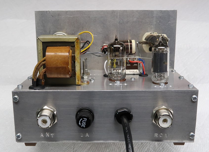
| Front View: The 6x2C converter is a 2 tube crystal controlled converter for the 30m and 20m bands. .When used with the 6x2 receiver the system comprises a 4 band double conversion superheterodyne receiver. The 6x2C covers the 30m band and the bottom 90 kHz of the 20m band. The 6x2 receiver covers 3500 kHz to 3850 kHz and 6900 kHz to 7250 kHz. When used with the 6x2C the frequency conversion is as follows: 30m: Input: 10100 kHz to 10150 kHz Output: 6954 kHz to 7004 kHz 20m: Input: 14,000 kHz to 14,090 kHz Output: 3760 kHz to 3850 kHz The input frequencies are perfect for a CW operator. The unusual output frequencies are the result of the only suitable crystals (3146 kHz and 10240 kHz) I was able to find over several years of searching. The front panel is brushed aluminum. Control functions are embossed into the panel using metal stamps. The two controls at left are the mixer grid tuning and antenna (RF amplifier grid) tuning. The band switch is at bottom center, and the RF gain control is at top right. The mode switch at bottom right has three positions as follows: Off: Power is off and the input is fed directly to the output. Standby: Power is on and the input is fed directly to the output. Run: Power is on and the converter circuit is switched in between the input and output. |
Click on the image for a larger view. Click here for a super detailed view. |
| Side View: I originally planned to have the converter powered by the accessory socket on the back of the 6x2 receiver. However, just before starting construction (but after making the chassis) I obtained a power transformer from a gutted Heathkit vacuum tube voltmeter. The transformer was perfect for the converter, so I decided to make the converter self powered. Fitting in the power supply proved to be difficult and resulted in the tightest point-to-point wiring I have ever done. The 6GH8 mixer/oscillator tube is at center and the 6BA6 RF amplifier is at right. The mixer grid circuit (cream colored coil and variable capacitor, are mounted on the front panel at right. These are isolated from the RF amplifier input by the top panel. (Good isolation between the RF amplifier grid and mixer grid is important to prevent oscillation in the RF amplifier.) |
Click on the image for a larger view. Click here for a super detailed view. |
| Rear View: In this rear view of the converter the power transformer is at left, the 6GH8 mixer/oscillator is in the middle, and the 6BA6 RF amplifier is at right. The oscillator tank coils can be seen just to the right of the power transformer. On the back panel the antenna input (ANT) is at left and the output (RCV) is at right. These are directly connected together in the Off and Standby modes. In the Run mode they are connected to the input and output of the converter circuit. Like the front panel the various functions are embossed into the metal using metal stamps. |
 Click on the image for a larger view. Click here for a super detailed view. |
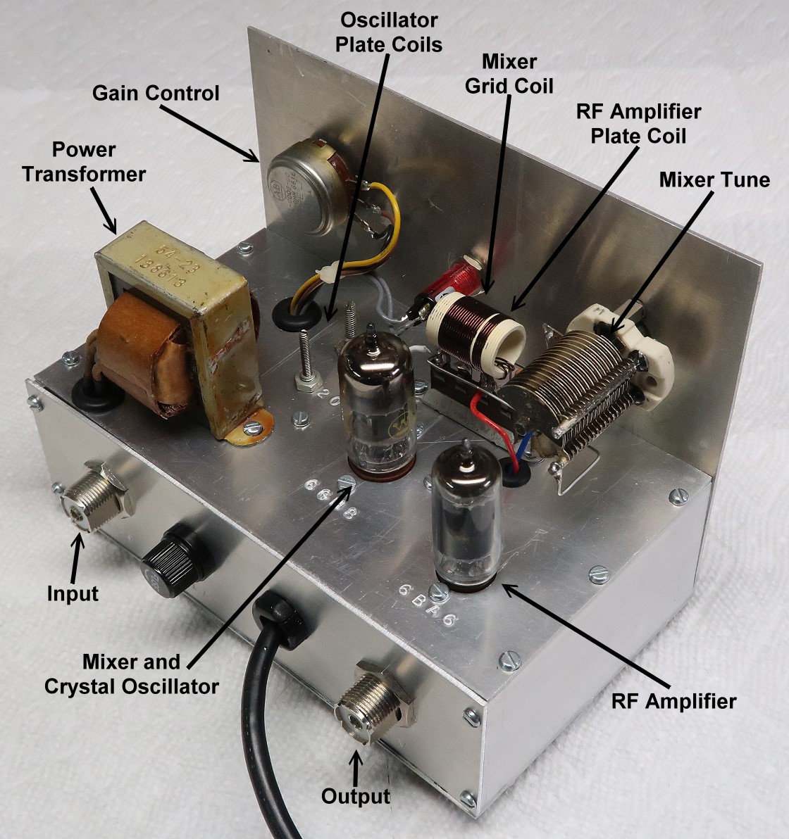
| Notated Side/Rear View: This is a notated view of the top and back of the converter as viewed from the side/rear. All of the parts mounted on the top of the converter and their functions are marked. (The 30m oscillator plate coil is a little hard to see behind and to the left of the 6GH8 mixer/oscillator tube.) Like the front and back panel, various functions and labels are embossed into the top panel using metal stamps. |
 Click on the image for a larger view. Click here for a super detailed view. |
 Back to Dr.
Greg Latta's Electrical Engineering and Amateur Radio Pages
Back to Dr.
Greg Latta's Electrical Engineering and Amateur Radio Pages
 If you have any questions or
comments, you can send E-Mail to Dr. Greg Latta at
glatta@frostburg.edu
If you have any questions or
comments, you can send E-Mail to Dr. Greg Latta at
glatta@frostburg.edu