Click on the image for a larger view.
Click here for a super detailed view.
Click on the image for a larger view.
Click here for a super
detailed view.
| 6x2C Crystal Controlled Converter - Main Page and Exterior Photos | Interior Photos |
| How To Operate The 6x2C Converter | Alignment and Voltage Table |
| Schematic Diagram and Circuit Descriptions | Mechanical Construction |
| Parts and Construction | Choosing Crystal Frequencies |
Initial Comments: |
Antenna and Mixer Input Components: |
Local Oscillator Components: Oscillator Coils L3 and L4 |
Power Transformer: |
Miscellaneous Components: Carbon Film Resistors - Through
Hole |
Electronics Parts SourcesMechanical Parts Sources |
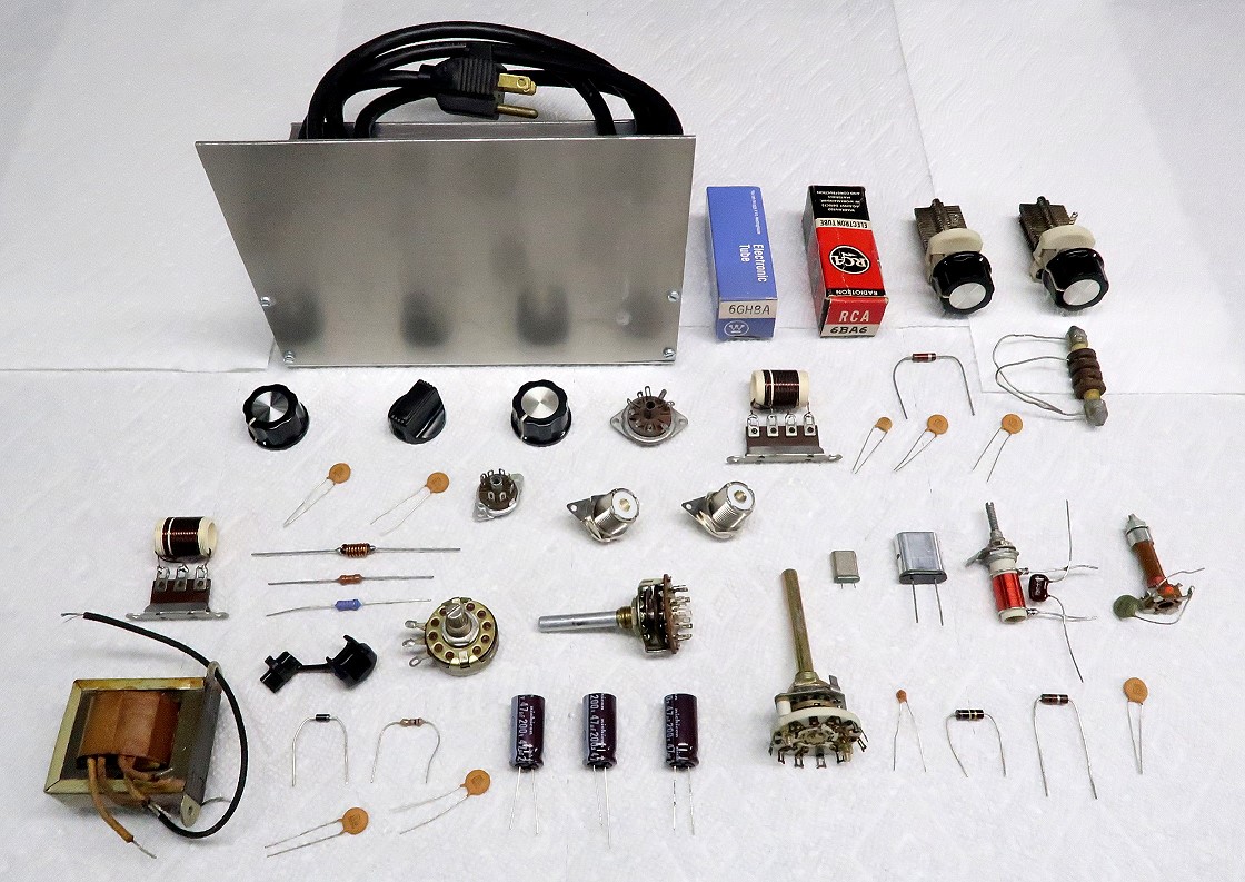
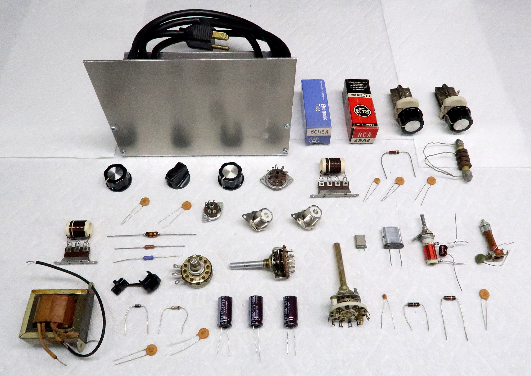
Introduction:
Building a converter such as the 6x2C is a challenging but rewarding project.
All of the parts for the 6x2C converter can be purchased new or made from
scratch. Some experimentation may be required, but the converter is much easier
to build than a project like the 6x2
receiver.
When building the 6x2C I recommend the following:
1. Before mounting on the chassis the crystal
oscillator should be breadboarded and tested with the actual crystals Y1
and Y2, coils L3 and L4, and capacitors C13 and C14 that will be used to make
sure it works properly.
2. Before mounting on the chassis the antenna input network L1 and C1 and the
mixer input network L2 and C2 should be tested to make sure they resonate on
the desired frequencies. They can be placed in parallel and tested with a grid
dip meter or they can be placed in series and tested with an antenna
analyzer/impedance bridge.
3. It is a good idea to work out the wiring around each tube socket on paper.
This can save a lot of grief.
4. Do not solder any connection until you are sure that no other items will
need to be soldered at that point.
5. The antenna L1/C1 and mixer L2/C2 networks must be isolated from one
another. One should be on the top of the chassis and the other on the bottom.
| Coils L1 and
L2: |
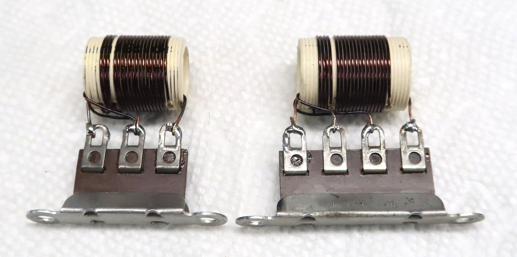 Coils L1 and L2 Click on the image for a larger view. |
| Capacitors C1 and
C2: |
 Capacitors C1 and C2 Click on the image for a larger view. |
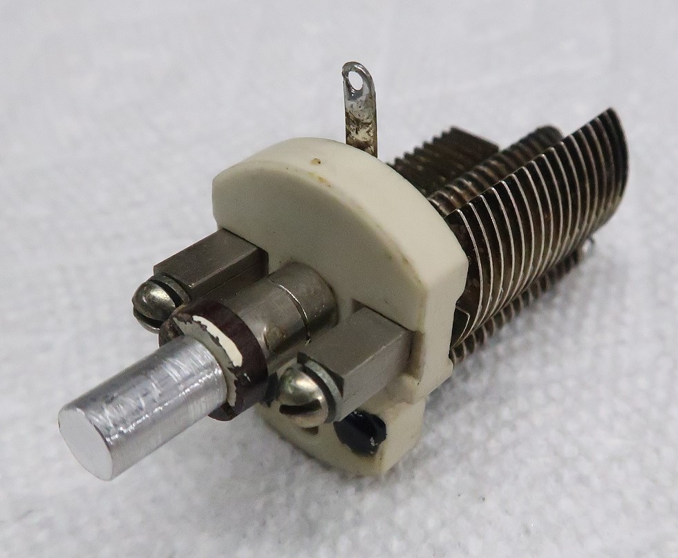
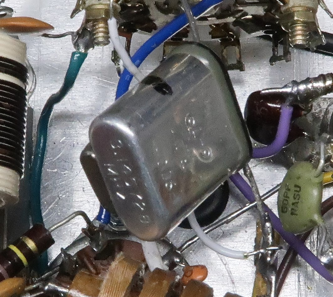
| Oscillator Coils L3 and L4: |
 Oscillator Coils L3 and L4 Click on the image for a larger view. |
|
| Crystals:
|
 Crystals Click on the image for a larger view. |
|
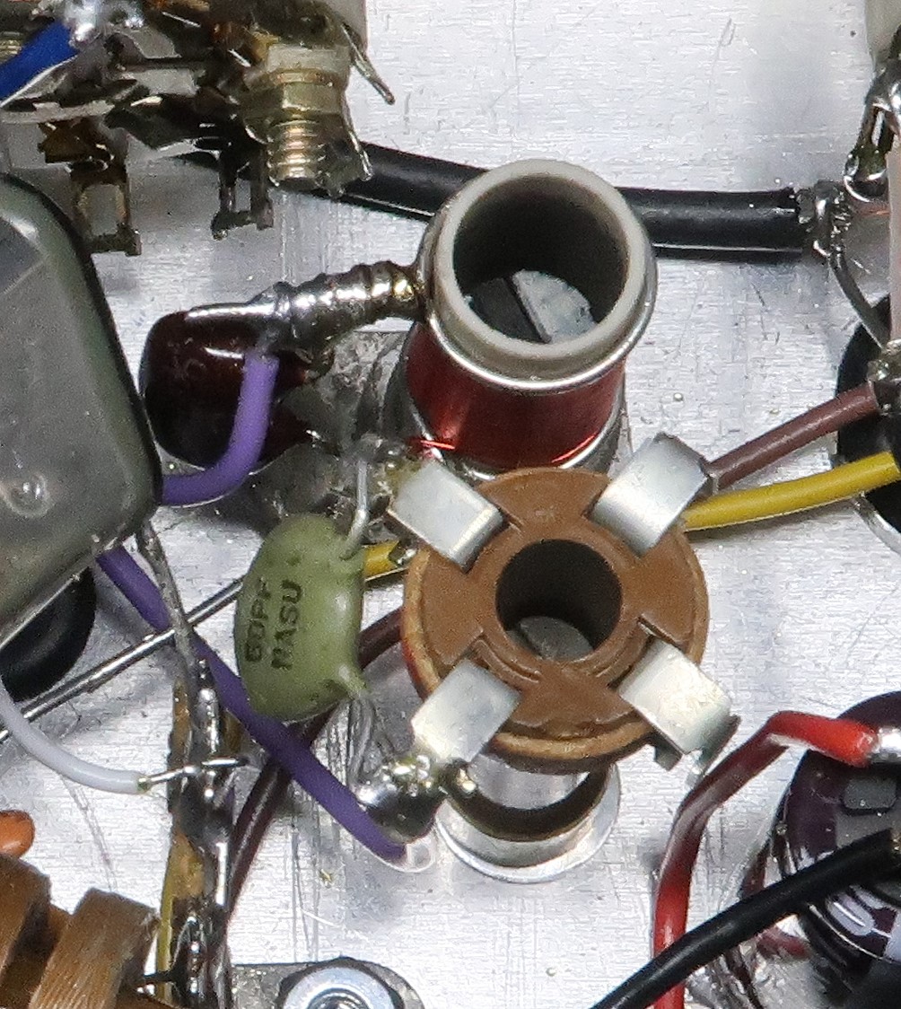
| Testing the
Local Oscillator: |
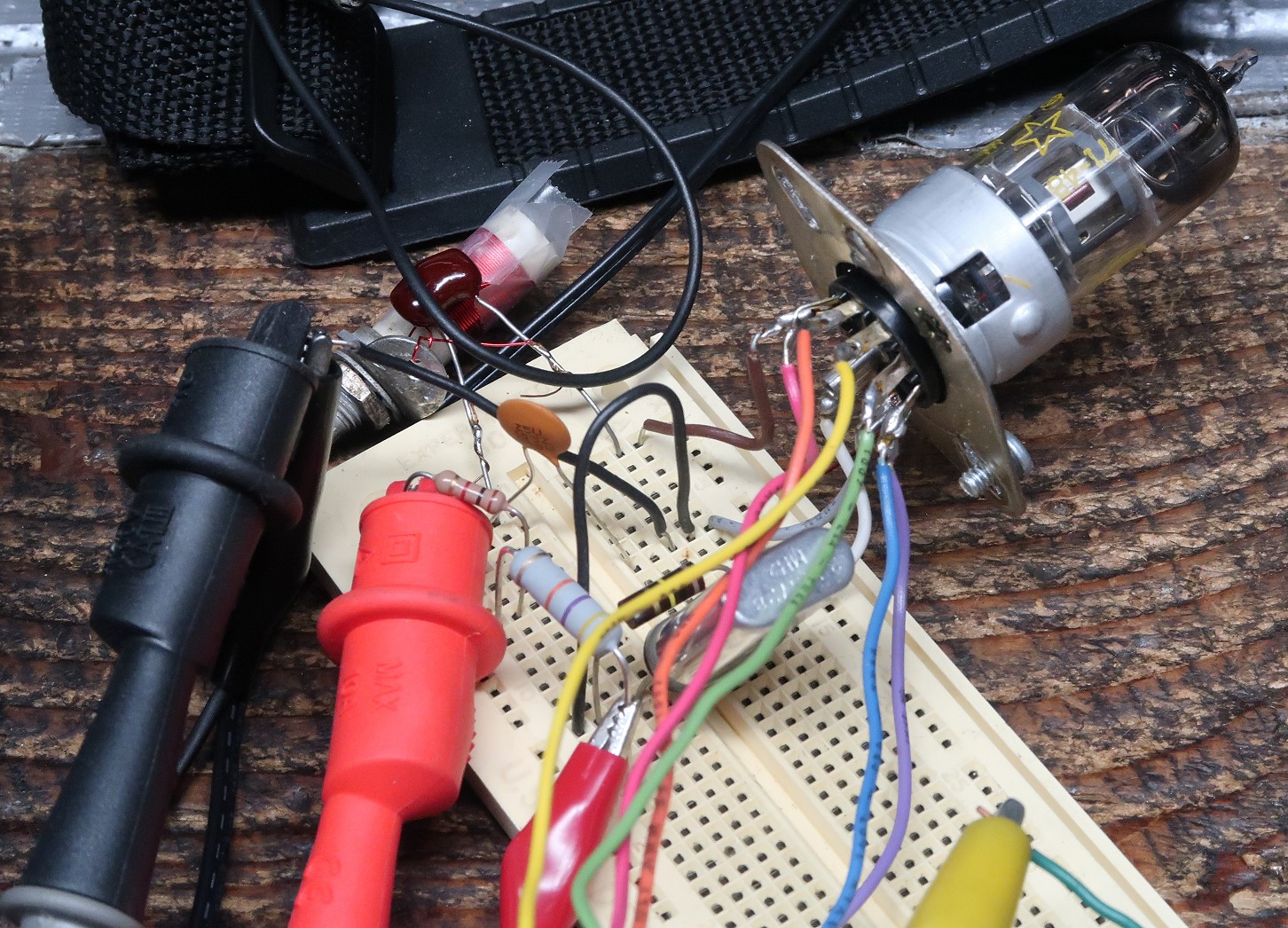 Oscillator Testing Click on the image for a larger view. |
|
| Transformer
Unrestored: |
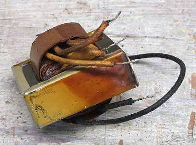 Transformer Unrestored |
| Transformer After Restoration: |
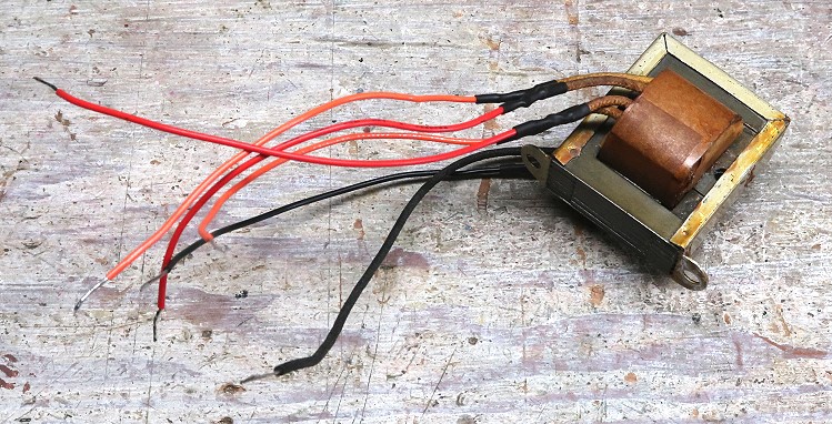 Transformer After Restoration |
| Power Transformer T1: |
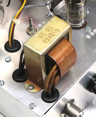 Power Transformer T1 Installed |
| Carbon Film
Resistors - Through Hole: |
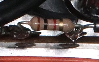 Carbon Film Resistors - Through Hole |
| Ceramic Disc
Capacitors: |
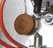 Ceramic Disc Capacitor |
| Terminal Strips:
|
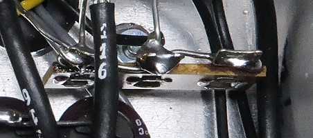 3-Lug Terminal Strip |
Though I have dealt with all of these sources, listing them does not constitute a legal endorsement of any kind.
Modern Electronic Parts:
Mouser Electronics, Digi-Key, and Arrow Electronics
Between Mouser Electronics, Digi-Key, and Arrow you should be able to find just
about any modern electronics component you could need. They carry resistors,
capacitors, semiconductors, screws and hardware, fans, potentiometers, encoders
etc. You name it, they have it. On the off chance one doesn't have what you
want the other will. They are happy to deal with small buyers such as you and
me. Their web sites are:
Mouser Electronics
Digi-Key
Arrow Electronics
RF Parts
RF Parts is a great source for both modern and classic parts. They carry a full
line of transmitting tubes along with dipped silver mica capacitors, ceramic
trimmer capacitors, variable capacitors, transformers, chokes, coaxial
connectors, terminal strips and much more.
RF Parts
Vintage and Surplus Electronic Parts:
Surplus Sales of Nebraska
As the name suggests, Surplus Sales of Nebraska deals in mostly surplus
equipment. They carry a good selection of ceramic trimmer capacitors, larger
variable capacitors, tubes, dipped silver mica capacitors, terminal strips,
transformers, and chokes. Transformers and chokes in particular can be
expensive, and can often be found surplus at attractive prices.
Surplus Sales of Nebraska
Antique Electronic Supply
Antique electronic supply now seems to cater heavily to the tube guitar
amplifier market. They carry a great selection of power transformers, chokes,
tubes, and other vacuum tube related parts, such as tube sockets, octal plugs,
terminal strips, and so on.
Antique Electronic Supply
Though I have dealt with all of these sources, listing them does not constitute a legal endorsement of any kind.
MSC Direct:
MSC Direct is a large industrial supplier. They are happy to work with small
individual buyers, and have monthly sales flyers that usually contain great
deals. They often have special sales where you can get free shipping or 10% to
30% off. I recommend getting on their mailing list to receive their monthly
sales flyers. They not only carry tools, but also raw materials, such as
aluminum and brass. If you wait for one of their special deals, you can get
your aluminum or brass on sale and get it shipped shipped free of charge too.
MSC Direct
OnLineMetals.com:
For any kind of metal or plastic you can't beat OnLineMetals.com. They carry
every conceivable metal and plastic in every form you can imagine.
OnLineMetals.com
 Back to Dr. Greg Latta's
Electrical Engineering and Amateur Radio Pages
Back to Dr. Greg Latta's
Electrical Engineering and Amateur Radio Pages
 If you have any questions or
comments, you can send E-Mail to Dr. Greg Latta at
glatta@frostburg.edu
If you have any questions or
comments, you can send E-Mail to Dr. Greg Latta at
glatta@frostburg.edu