
Click on the image for a larger view.
Click here for a super detailed view.
| 6x2C Crystal Controlled Converter - Main Page and Exterior Photos | Interior Photos |
| How To Operate The 6x2C Converter | Alignment and Voltage Table |
| Schematic Diagram and Circuit Descriptions | Mechanical Construction |
| Parts and Construction | Choosing Crystal Frequencies |
Comments:
Below are interior pictures of the converter. The converter design is based on
a circuit in the 1965 ARRL Handbook. The circuit in the Handbook, however, uses
a 6BZ6 as the RF amplifier and a 6U8 as the mixer/oscillator. The 6BZ6 is hard
to find and somewhat expensive nowadays, so I used a circuit based on the 6BA6,
which is inexpensive and much easier to find. Except for the input and output
coupling, the circuit I used for the RF amplifier is identical to the IF
amplifier in the 6x2 superheterodyne
receiver. From experience with my 6x2
receiver I found that the 6GH8 performs better than the 6U8 and can be
substituted without any circuit or wiring changes. A 6EA8 might also be used as
well. The power supply circuit is the same as that in the 1965 Handbook but
with larger capacitances based on what I had on hand in my stock pile.
| RF Input |
| RF Amplifier |
| Band Switch |
| Oscillator Crystals and Plate Coils |
| Mixer |
| Mode Switch |
| Power Supply |
Or
Click On Any Part Of The Picture
Below For Information On That Part Of Converter

Click On Any Part Of The Picture Above For
Information On That Part Of The Converter
| RF Input: This picture shows the antenna input circuit consisting of capacitor C1 and coil L1. The coax bringing the antenna signal in from the mode switch can be seen at top right. Coil L1 is wound on a coil form made from 1/2" ID CPVC plumbing pipe that has been lightly threaded on a lathe at 32 threads per inch. The primary at top consists of 3 turns of #23 magnet wire. The secondary at bottom consists of 15 turns of #23 magnet wire separated 1/32" from the primary. Mixer coil L2 is identical to L1 except that it has 4 turns on the primary. When measured with an MFJ antenna analyzer, the secondary measures 3.74 uH at 10.1 MHz and resonates at 10.1 MHz with 66 pf of capacitance. It measures 4.47 uH at 14.0 MHz and resonates at 14.0 MHz with 28 pf of capacitance.. |
 Click on the image for a larger view. Click here for a super detailed view. |
| RF Amplifier: A 6BA6 is used as the RF amplifier. Except for the input and output coupling this RF amplifier circuit is the same as the IF amplifier circuit in the 6x2 superheterodyne receiver. The 6BA6 tube socket is located in the center of the picture. Input RF choke RFC1 wound on resistor R2 can be seen at top left. The output connector can be seen at bottom center. Note the method used to attach the coax to the connector. The coax shield is removed until only 1/8" is left. Solid hookup wire is then wrapped around the shield, trimmed, and then carefully soldered. The hookup wire is then connected to the appropriate point. This results in a sturdy, secure connection that prevents the end of the coax from moving. |
 Click on the image for a larger view. Click here for a super detailed view. |
| Band Switch: The band switch is a ceramic Centralab 3 pole-3 position rotary switch. Only two poles are used. The switch also has a position limiter that is set so that it only has two positions. One pole switches between Y1 and Y2, and the other pole switches between L3 and L4. |
 Click on the image for a larger view. Click here for a super detailed view. |
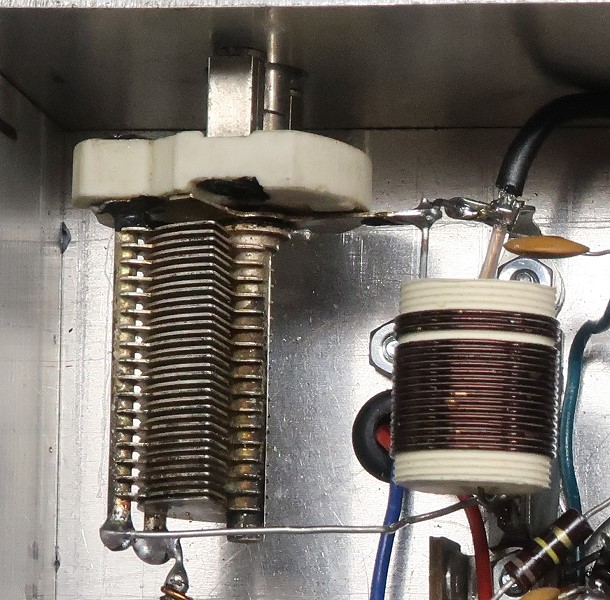
| Oscillator Crystals and Oscillator Plate Coils: Each band requires a crystal and associated plate coil. In this picture Y1, the 3.146 MHz crystal for 30m, can be seen at left. Crystal Y2, the 10.24 MHz crystal for 20m, is smaller and barely visible underneath Y1. Coil L3, the 30m coil, is at top right, and coil L4, the 20m coil, is at bottom right. Coil L3 consists of 38 turns of #29 magnet wire close wound on a 3/8" diameter powdered iron core coil form. It has an inductance of 10.6 uH with the slug fully out and resonates at 3.21 MHz with a 240 pf capacitor across it. Coil L4 is a North Hills 120-8 coil. It is rated at 3 uH -5 uH. With the slug in the middle of the windings it measures 5.54 uH at 10.24 MHz and resonates at 10.24 MHz with a 43 pF capacitor across it. |

Click on the image for a larger view. Click here for a super detailed view. |
| Mixer: The wiring in the 6x2C converter is very tight. This is particularly true around the 6GH8 mixer/oscillator. The tube socket can barely be seen at the center of this photo. RF choke RFC2 (bottom) and crystal Y1 (top) dominate the photo. Crystal Y2, which is smaller than Y1, can barely be seen underneath Y1. The output coaxial cable can be seen connected to the output of the mixer at lower left. (The coil at top left is the input coil L1, not L2, the mixer coil, which is on top of the chassis.) |
 Click on the image for a larger view. Click here for a super detailed view. |
| Mode Switch: Like the band switch the mode switch is also a ceramic Centralab 3 pole-3 position rotary switch. Two of the poles handle the RF switching, and the other pole handles the AC power. The mode switch has three positions: Off: The power is off. The antenna input is connected to the output to the receiver. The converter is bypassed. Standby: The power is on. The antenna input is connected to the output to the receiver. The converter is bypassed. Run: The power is on. The antenna input is connected to the converter input. The converter output is connected to the output to the receiver. The converter is switched in. This arrangement allows the converter to be quickly switched in and out with the power on. This makes proper adjustment of the converter and receiver much easier. |
 Click on the image for a larger view. Click here for a super detailed view. |
| Power Supply: The power supply is a simple half wave rectifier followed by a pi filter. The converter requires very little current so a half wave circuit is more than adequate. Capacitors C4 and C5 are in parallel and can be seen at top right. Diode CR1 and resistor R7 are mounted on a terminal strip at center. Capacitor C3 is just above diode CR1. Fuse F1 at bottom left protects the AC primary circuit. The input connector can be seen at bottom right. Note the method used to attach the coax to the connector. The coax shield is removed until only 1/8" is left. Solid hookup wire is then wrapped around the shield, trimmed, and then carefully soldered. The hookup wire is then connected to the appropriate point. This results in a sturdy, secure connection that prevents the end of the coax from moving. |
 Click on the image for a larger view. Click here for a super detailed view. |
 Back to Dr. Greg Latta's
Electrical Engineering and Amateur Radio Pages
Back to Dr. Greg Latta's
Electrical Engineering and Amateur Radio Pages
 If you have any questions or
comments, you can send E-Mail to Dr. Greg Latta at
glatta@frostburg.edu
If you have any questions or
comments, you can send E-Mail to Dr. Greg Latta at
glatta@frostburg.edu