| Using the LM-13 Frequency Meter As A VFO - Main Page | Replacing the Neon Lamps with a 0A2 Regulator Tube |
| Power Supply | Grid Blocking the Oscillator During ReceiveNew! |
| 2 Transistor Buffer Amplifier and 1 to 2 Voltage Step Up Transformer Page | Schematic Diagram and Circuit Descriptions See Link Below |
| How to Read a Vernier Scale | Making an Aluminum Case for the LM-13 New! |
| Exterior Photos | Interior Photos |
| Resources and Manuals See Link Below | Restoration and Testing |
| Introduction |
| Schematic Diagram for the LM-13 |
| Modified Schematic Diagram for the LM-13 |
| Calibration Crystal |
| Resources and Manuals |
Introduction:
When I sold my 10 year old TenTec Jupiter to a friend and new ham, part of the
payment to me was an old beat up piece of WW II equipment given to him by
another ham. It was in sad shape but on closer inspection it turned out to be a
1941 US navy LM-13 frequency meter. When I dug a little deeper I found that the
LM-13 was a high precision piece of WW II equipment. It contained, among other
things, a precision oscillator that operated on two ranges, one of which was
2000kHz to 4000kHz. If it was a precision oscillator, perhaps it would be
stable enough to be used as a VFO on the 80m band. Close inspection showed that
the LM-13 was complete, but with no power supply and no cover. If I could
design and build a power supply for it and make a cover, there was indeed a
good chance that it could serve as an 80m VFO.
The first task was to build a power supply for it and get it running. I could
then determine how stable it was and whether it was stable enough to serve as a
VFO. It was relatively easy to find the manual for it on-line. I have listed
links to manuals and other documentation on the LM-13 in the tables above. It
turns out the power requirements were very easy to meet. You can read about the
power supply I designed and built for the LM-13 here:
Power Supply for the LM-13
Frequency Meter
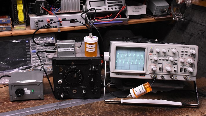
I thoroughly checked out the LM-13 and had to resolder a couple of questionable
connections, but overall the circuitry was in excellent shape, a testimony to
the original quality with which it had been built. Connecting a bread-boarded
power supply immediately brought it back to life with a clean, stable signal.
Listening on a receiver and looking at the signal on my spectrum analyzer
showed that the signal was very clean and very stable. There was some turn on
drift when the plate voltage was first turned on, but the frequency would
settle down after perhaps ten seconds. This was too long to make it useful as a
VFO unless I could find a way to lessen the turn-on drift. I experimented with
grid-blocking the oscillator tube and found that this was a great improvement.
When the blocking voltage was removed, the oscillator promptly started with a
slight "swoop" that lasted only about 1-2s. If I waited about 1s when
starting a QSO, and did not key the oscillator, the oscillator would be
stabilized and remain so throughout the QSO. Conclusion: the LM-13 could indeed
serve as a VFO, though it could not be keyed.
Another problem with using the LM-13 as a VFO was it's very low output. The
LM-13 oscillator, though very stable, wasn't designed to drive anything other
than its own internal mixer, and the output was only 200-300mV peak-to-peak.
This would have to be raised to at least a couple of volts peak-to-peak if the
LM-13 were to serve as a VFO. As it turns out, a
2 Transistor buffer
amplifier and 1 to 2 voltage step up transformer could be built that would
do the job.
With all of the interruptions I had it took over a year to get the LM-13 on the
air, but on February 13th, 2018 I made my first QSO with it. While I was
testing the system on 40m, another station gave me a call and I worked him with
no trouble at all! As it turns out, my LM-13 VFO system has enough drive to
operate my 6146B transmitter on both 80m and 40m. It is as stable as a modern
transceiver and very easy to tune. It was well worth the effort to get it on
the air!
Schematic Diagram for the
LM-13:
Below is the schematic diagram for the LM-13 frequency meter. This was taken
from the Handbook of Maintenance
Instructions. Click on the image or the link for a larger version suitable
for printing.

Modified Schematic Diagram for
the LM-13:
Below is the schematic diagram of my LM-13 where the following modifications
have been implemented:
1. The filament circuit has been modified for 6 V operation. I don't recommend
this but this is how I received my LM-13, so I didn't change it.
2. The power connector has been changed to a 6 pin Cinch-Jones connector.
3. The neon bulbs have been changed to a single 0A2. Resistor R-103 has been
changed to 17.5 kohm for proper operation with my 245 V B+ power supply. My
resistor is a 7W unit but anything over about 2W should be OK with a 245 V B+
supply.
4. A 10 uf , 450 V capacitor has been placed across the B+ line in the LM-13
unit itself to filter out the small ripple introduced by the filament
current voltage drop in the ground lead of the power supply connecting cable.
5. Grid block control of the oscillator has been implemented. Placing -16V or
greater on the blocking bias line will cutoff and disable the oscillator.

Calibration Crystal:
The calibration crystal in the LM-13 is an amazing unit, even today. The
crystal is in a hermetically sealed case with an octal socket. The crystal
specifications are as follows:
Type: Cut "AT" Crystal
Frequency: 1000 KHz ± 10 Hz=1,000,000 Hz ± 10 Hz
Temperature Coefficient: 0.0001% / °C=1 Hz /°C
Calibration Temperature: 20°C
This means that, even without calibration against a frequency reference such as
WWV, when used in the LM-13, the frequency of the crystal at room temperature
would be within 10 Hz of 1 MHz! Between 0°C and 40°C, which is the
probable range over which the LM-13 would be used, the crystal would be within
30 Hz of 1 MHz. This is amazing accuracy, especially for 1941!
Resources and Manuals:
Handbook of Maintenance
Instructions - Be sure to download and save this! This is "the
book" on the LM-13.
Calibrating Equipment - L
Series
Surplus Radio Conversion
Manual
QST Article from September 1965
©Copyright Statement:
All images, designs, and materials on these web pages are the property of
Gregory P. Latta and are ©2018 by Gregory P. Latta. You may use them for
personal purposes and for educational purposes, but any commercial or other use
is strictly prohibited unless written permission is obtained from the author.
 Back to Dr.
Greg Latta's Electrical Engineering and Amateur Radio Pages
Back to Dr.
Greg Latta's Electrical Engineering and Amateur Radio Pages
 If you have any questions or
comments, you can send E-Mail to Dr. Greg Latta at
glatta@frostburg.edu
If you have any questions or
comments, you can send E-Mail to Dr. Greg Latta at
glatta@frostburg.edu