
| Using the LM-13 Frequency Meter As A VFO - Main Page | Replacing the Neon Lamps with a 0A2 Regulator Tube |
| Power Supply | Grid Blocking the Oscillator During Receive |
| 2 Transistor Buffer Amplifier and 1 to 2 Voltage Step Up Transformer Page | Schematic Diagram and Circuit Descriptions |
| How to Read a Vernier Scale | Making an Aluminum Case for the LM-13 |
| Exterior Photos | Interior Photos |
| Resources and Manuals |
Introduction:
The voltage applied to the oscillator in the LM-13 must be regulated if the
oscillator is to be stable. Though a conventional gaseous voltage regulator
(VR) tube could be used to provide the regulation, the oscillator draws only a
couple of mA of current, and a conventional VR tube would have been much larger
than needed. At at the beginning of WWII there were no miniature 7-pin
regulator tubes such as the 0A2, and the use of one of the then available VR
tubes would have substantially increased the size of the LM-13. To save
valuable space, neon bulbs were used as regulators instead. The nominal voltage
drop across a single neon bulb (without an internal dropping resistor) is 60 V
to 70 V. Thus two in series would give a total of 120 V to 140 V, ideal for
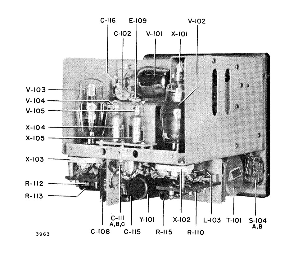
regulating the voltage on the oscillator. In the image below, taken from page
36 of the manual, the neon regulator bulbs are V-104 and V-105. The bulb
sockets are labeled X-104 and X-105
Click on the image or here for a larger view.
The neon regulator bulbs and their sockets are labeled V-104/X-104 and
V-105/X-105 in this picture from page 36 of the LM-13 manual.
Replacing The Neon Lamps With An 0A2:
It is unfortunate that in many LM-13s the neon bulbs are now missing, and they
are now nearly impossible to find. It is very easy to replace the neon bulbs
with a 0A2 regulator tube. The platform holding the bulb sockets must be
removed and replaced with a new platform holding a 7-pin tube socket as can be
seen in the photo below:
Click here for a larger view.
In this view taken from the back of the LM-13 the platform holding the neon
bulbs has been replaced with a new one made from bakelite.
The new platform holds a 7-pin tube socket and 0A2 regulator tube. Although
this tube socket takes a tube shield, a shield is not necessary.

Click here for a larger view.
In this view, the tube shield has been installed on the 0A2.
The tube is wired so that the anode (pin 1 or 5) is connected to R-116 and the cathode (pin 2, 4, or 7) is connected to ground. See the schematic below:

The tube is wired so that the anode (pin 1 or 5) is connected to R-116 and the
cathode (pin 2, 4, or 7) is connected to ground.
Choosing the Proper Value and Power Rating of the Dropping
Resistor:
Once the 0A2 is installed, it is necessary to determine the proper value for
the dropping resistor. When the LM-13 is used as a VFO, the proper value
guarantees enough current through the VR tube to keep it stable and lit, and
enough current for the oscillator tube for proper oscillation. I have found
that a total current through the dropping resistor of 5 mA to 6 mA seems to
work just fine. More than this just produces excess heat and loads down the
power supply, and less results in unstable operation of the VR tube.
The proper value of the dropping resistor is easy to calculate. First, find
the needed voltage drop by subtracting the VR tube voltage (150 V) from the
value of your B+:
VDROP = Your B+ - 150 V
Next, divide the voltage drop by 0.005 A to get the required resistance:
RDROP = VDROP / 0.005 A
Finally, to get the power dissipated in the dropping resistor, multiply the
voltage drop by 0.005 A:
PDISSIPATED = VDROP x 0.005 A.
Double or triple this value as a safety factor to get the power rating
of the dropping resistor.
Let's do an example. My
power supply puts out 245 V so:
VDROP = 245 V - 150 V=95 V
We divide this by 0.005 A to get the resistance:
RDROP = VDROP / 0.005 A = 95 V / 0.005 A = 19000
ohm or 19 kohm
The power dissipated is VDROP x 0.005A:
PDISSIPATED = 95 V x 0.005 A = 0.48 W
Tripling this gives 3 x 0.48 W = 1.43 W. So a 19 kohm 2 W resistor
would be perfect.
In actuallity, I used a 17.5 kohm 7 W resistor I found in my junk box that was
close in physical size to the original R-103. This gives a current of 95 V /
17500 ohm = 5.4 mA which is close enough to the ideal 5 mA.
Installing The New Dropping Resistor:
The easiest way to get the required dropping resistance is to first set the
link on the link panel so that R-116 is not in the circuit as shown on the
schematic diagram above. R-116 is hard to get to and is probably best left
alone. The link panel and R-116 can be seen in the photo below. The link panel
is half way down on the left, and R-116 is very near the center of the photo.

In this photo, taken from page 39 of the LM-13 manual, the link panel can be
seen at left center,
R-116 is near the center of the photo, and R-103 can be seen at top right.
With the link set to bypass R-116, all of the drop resistance can be placed at the location of R-103. R-103 is very easy to get to and is located at the upper right in the photo above. The original resistance of R-103 is 25 kohm. If the required dropping resistance is less than 25 kohm, you can add resistance in parallel with R-103 to lower the effective resistance to the new value. If the required resistance is larger than 25 kohm, you can unsolder one end of R-103 and add resistance to bring the effective resistance up to the required value. You can also simply replace R-103 with a new resistor if you like, but if possible I suggest that you keep the original R-103 for historical reasons.
Once you have everything installed you can power up the LM-13 and check to see if everything is working OK. You should have 150 V across the 0A2 tube and the tube should be lit. (It may be hard to see if it is lit, so darken the room if necessary.) You can verify the current through the dropping resistance by measuring the voltage across it (be careful, both sides are above ground!) and dividing by the total resistance to get the current. It should be around 5 mA.
©Copyright Statement:
All images, designs, and materials on these web pages are the property of
Gregory P. Latta and are ©2017 by Gregory P. Latta. You may use them for
personal purposes and for educational purposes, but any commercial or other use
is strictly prohibited unless written permission is obtained from the author.
 Back to Dr. Greg Latta's
Electrical Engineering and Amateur Radio Pages
Back to Dr. Greg Latta's
Electrical Engineering and Amateur Radio Pages
 If you have any questions or
comments, you can send E-Mail to Dr. Greg Latta at
glatta@frostburg.edu
If you have any questions or
comments, you can send E-Mail to Dr. Greg Latta at
glatta@frostburg.edu