
| Using the LM-13 Frequency Meter As A VFO - Main Page | Replacing the Neon Lamps with an 0A2 Regulator Tube |
| Power Supply | Grid Blocking the Oscillator During Receive |
| 2 Transistor Buffer Amplifier and 1 to 2 Voltage Step Up Transformer | Schematic Diagram and Circuit Descriptions |
| How to Read a Vernier Scale | Making an Aluminum Case for the LM-13 |
| Exterior Photos | Interior Photos |
| Resources and Manuals |
Filament Wiring and Filament Power Supply
Requirements:
During WWII, one never knew what power supply might be available for use with
the LM-13, so it was designed with power supply flexibility in mind. The three
tubes all have 6 V (actually, 6.3 V), 0.3 A filaments, but they are wired so
that the filaments can be run off of either 12 V or 24 V.
The filaments of the 77 oscillator and 6A7 mixer are wired in series as a 12 V
branch circuit. The filament of the 76 audio tube is wired in series with a 20
ohm voltage dropping resistor (R-113) as another 12 V branch circuit. These two
branch circuits can then be run either in parallel (12 V at 0.6 A) or in series
(24 V at 0.3 A) by changing the settings on the internal
link panel.
Since all three tubes use 6 V filaments, it is possible to bypass R-113 (don't
remove it!) and also wire the filaments of the 77 oscillator and 6A7 mixer in
parallel and run all three tubes in parallel from a 6 V, 0.9 A supply. This is
how my LM-13 was wired when I got it, and I did not change it.
B+ Power Supply Requirements:
Voltage Requirement:
The LM-13 is very forgiving as to the requirements for the B+ supply.
Flexibility was important in war time, and it is certainly apparent in the
LM-13 was designed with flexibility in mind. The LM-13 can be used with a B+
supply from 200 V to 475 V. Full B+ is placed on the mixer and audio circuits,
but lower B+ voltage regulated by a pair of neon lamps in series, which act as
a gaseous regulator tube like the 0A2, is applied to the oscillator. An
internal link panel selects R-103 as the dropping
resistor for the voltage regulators if the B+ is between 200 V and 260 V. If
the B+ is higher, between 260 V and 475 V, then the link
panel is set to place R-116 series with R-103. It is not necessary for the
B+ to be regulated since the LM-13 internally regulates the voltage on the
oscillator.
Current Requirement:
Very little current is needed to operate the LM-13. I find that with a 245 V B+
my LM-13 draws only 13 mA. 20 mA might be a conservative estimate of the
maximum current required.

Click here or on the image for a larger view.
In this picture, taken from page 39 of the operating manual, the internal
link panel that is used to
change the filament and B+ wiring can be seen at left center in the photo.
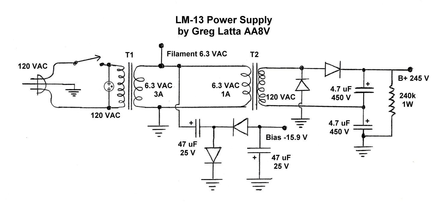
My Power Supply:
Since my LM-13 was modified to use 6.3 V on the filaments, and the B+ current
requirement was so small, I decided to use a 6.3 V, 3 A filament transformer to
step the line voltage down to 6.3 V. This transformer would then power the
filaments, but would also drive another 6.3 V transformer run backwards to step
the voltage back up to 120 V. The 120 V from the second transformer would be
applied to a full wave voltage doubler to produce about 245 V for the LM-13 B+.
I also needed about -16 V of bias to cut off the 77 oscillator tube during
receive periods and to operate a small relay for T/R switching. The 6.3 VAC for
the filament supply could be applied to a half wave voltage doubler to get the
required bias, since you can't use a full wave voltage doubler when one side of
the transformer is grounded. The half wave voltage doubler doesn't need to
provide much current to cut off the oscillator, only about 0.1 mA. The 12 V T/R
relay needs much more current, but I found that when I connected it to the half
wave voltage doubler, the output dropped down to about 7 V. Even though the
relay coil is rated at 12 V, it still pulled in reliably with only 7 V, so I
decided not to use a separate supply for the relay.
My Power Supply Schematic Diagram
The schematic diagram for my power supply is shown below:
Click here for a larger image suitable for printing.
Power Supply Changes:
The above power supply can be easily modified to match your situation. For
example, if your LM-13 filament circuit is unmodified, set it up for 12 V
operation and replace the 6 V transformers above with back to back 12 V, 1 A
transformers.. A simple half wave rectifier can then be used for the bias,
rather than a half wave doubler.
| Front View of the Finished Power Supply: This is a front on view of the finished power supply. The power supply is built in a 3"H x 4"D x 5"W minibox that I happened to have on hand. The AC power cord, transmit/receive jack, and the power cord running to the LM-13 exit the back panel. The mode switch and pilot lamp occupy the front panel. The mode switch has three positions, which were were not labeled when the picture was taken. The three positions and their functions are as follows: 1. Off 2. Receive/Standby -:Both filament and B+ are applied to the LM-13. Blocking bias is applied to the oscillator tube. 3. Transmit/Operate - Both filament and B+ are applied to the LM-13. The blocking bias is removed from the oscillator tube. When in Receive/Standby mode, the power supply can be placed remotely in Transmit/Operate mode by shorting the center pin of the transmit/receive jack on the back panel to ground. |
 Click on the image for a larger view. Click here for a super detailed view. |
| Interior View of the Power Supply with Notations: The various components of the power supply are easily identified in this interior view of the power supply. The voltage doublers are mounted on small printed circuit breadboards on either side of the front panel. The full wave B+ voltage doubler is at the lower left in the photo, and the half wave bias voltage doubler is at upper left in the photo. T1, the larger 3A transformer is at bottom right in the photo and T2, the smaller 1A transformer, is just above it. The small hermetically sealed T/R relay is glued to the top of T1 with hot melt glue, which works great in this application. The gray power cable and AC power cord can be seen at right in the photo. Connections to the gray power cable to the LM-13 are as follows: Red - B+ Black - 6.3 VAC filament White - -15.9 VDC blocking bias (in Transmit/Operate mode only) Bare Wire and Shield - Ground (Barely visible in the photo under a white wire where it connects to the left lug of T2) The transmit/receive RCA jack can be seen at top right in the photo. When the power supply is in Receive/Standby mode, shorting this jack to ground places the power supply in Transmit/Operate mode. |
 Click on the image for a larger view. Click here for a super detailed view. |
| View of Complete power Supply: In this picture of the completed power supply the AC power cord can be seen at the left and the power cord to the LM-13 can be seen at right. The power cord to the right should have a FEMALE connector on the end, not the male connector as shown! My LM-13 already had a female connector mounted on it, and I could not find a male connector, so I had to go with what I had. The problem is that high voltage is present on the male end as shown when the power supply is turned on. In such a case the power supply must not be turned on unless it is connected to the LM-13. Otherwise, high voltage is exposed. I have seen this problem even on some commercially produced equipment, so always remember, SAFETY FIRST. |
 Click on the image for a larger view. Click here for a super detailed view. |
©Copyright Statement:
All images, designs, and materials on these web pages are the property of
Gregory P. Latta and are ©2017 by Gregory P. Latta. You may use them for
personal purposes and for educational purposes, but any commercial or other use
is strictly prohibited unless written permission is obtained from the author.
 Back to Dr. Greg Latta's
Electrical Engineering and Amateur Radio Pages
Back to Dr. Greg Latta's
Electrical Engineering and Amateur Radio Pages
 If you have any questions or
comments, you can send E-Mail to Dr. Greg Latta at
glatta@frostburg.edu
If you have any questions or
comments, you can send E-Mail to Dr. Greg Latta at
glatta@frostburg.edu