 Click on the image for a larger view. Front Panel Before Restoration |
 Click on the image for a larger view. Front Panel After Restoration |
| Click on the image for a larger view. Front Panel Before Restoration |
Click on the image for a larger view. Front Panel After Restoration |
| Using the LM-13 Frequency Meter As A VFO - Main Page | Replacing the Neon Lamps with an 0A2 Regulator Tube |
| Power Supply | Grid Blocking the Oscillator During Receive |
| 2 Transistor Buffer Amplifier and 1 to 2 Voltage Step Up Transformer | Schematic Diagram and Circuit Descriptions |
| How to Read a Vernier Scale | Making an Aluminum Case for the LM-13 |
| Exterior Photos | Interior Photos |
| Resources and Manuals |
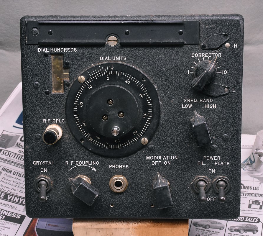
| LM-13 Front Panel Before Restoration: When I received my LM-13 it was in poor shape. It had no case and no power supply. It was covered with dirt and dust and there was some corrosion on the chassis. This is a picture of the front panel before I did any work on it. All of the original knobs were present, and the tuning mechanism worked fine. Initial inspection showed that the wiring was in good shape, at least at first glance. |
 Click on the image for a larger view. Click here for a super detailed view. |
| LM-13 Front Panel After Restoration: When I closely inspected the wiring and made checks with an ohmmeter I found a loose connection in the oscillator. This was very easy to get to and was quickly repaired. Further checking showed that the filament circuit had been modified for 6 V operation, rather than the original 12/24 V operation. A temporary power supply was quickly put together and the LM-13 was found to operate beautifully. The oscillator was stable and produced a clean signal. After proper operation was verified, I began the work of cleaning up the front panel and the chassis. All of the knobs were removed and scrubbed down with Formula 409 and Soft Scrub to remove many years of dirt and patina. They were then coated with Pledge furniture polish which restored their nice black finish. The black wrinkle finish on the front panel was cleaned with Q-tips and lighter fluid (naptha). The naptha removes grease and other dirt without affecting the paint. This was followed with Pledge furniture polish applied with Q-tips. This restored the deep black appearance of the wrinkle finish. Other than some unavoidable wear and tear on the knobs, the front panel looks almost as good as it did the day it left the factory! |
 Click on the image for a larger view. Click here for a super detailed view. |
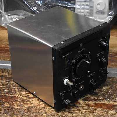
| LM-13 In New Aluminum Case: My LM-13 did not have a case. I made a case for it out of aluminum sheet as can be seen in the photo. The case tightly seals the chassis and provides additional stability. You can learn about the case and how it was made by going to Making an Aluminum Case for the LM-13. |
 Click on the image for a larger view. Click here for a super detailed view. |
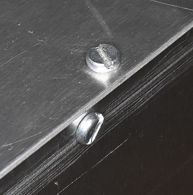
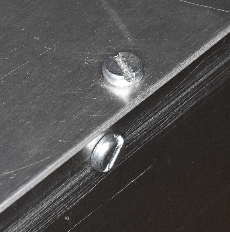
| Method of Fastening the Sides of the Aluminum Case: To provide a tight RF enclosure and to stiffen the new case the edges were secured to each other with 4-40 screws. The screws fit into small blocks made from 1/4" square aluminum bar stock. In this photo, the screws can be seen on the exterior of the case. To read more about the blocks, you can click here. |
 Click on the image for a larger view. Click here for a super detailed view. |
| Power Supply: The LM-13 lacked a power supply. However, the power requirements were quite forgiving, and I was able to design and build a power supply that fit into 3" x 4" x 5" minibox. The power supply also allows the LM-13 to be remotely placed in transmit or receive mode and to be spotted in the receiver. To learn more abut the power supply, you can go to the LM-13 Power Supply Page. |
 Click on the image for a larger view. Click here for a super detailed view. |
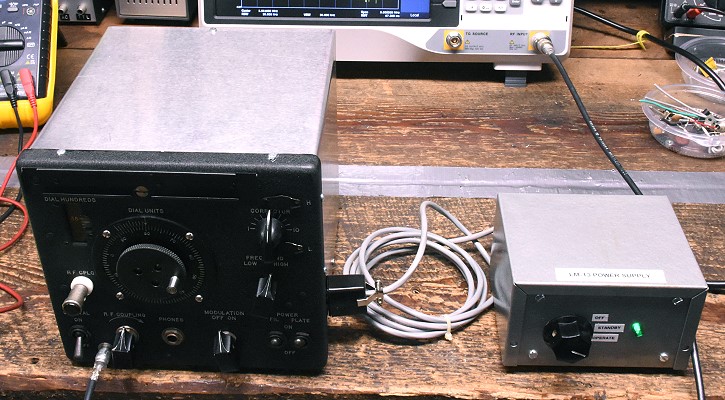
| Restored LM-13 and Power Supply: This is a picture of the LM-13 in its new aluminum case along with the power supply. The power supply connects to the LM-13 through a cable that allows them each to be positioned as needed. The power supply can be used to turn on the LM-13 for spotting purposes, and the LM-13 can be placed in transmit mode by connecting an RCA jack on the back of the power supply to ground. The connection to ground is normally done by my automatic T/R system, which also switches the antenna and mutes the receiver. |
 Click on the image for a larger view. Click here for a super detailed view. |
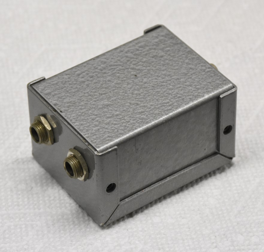
| Two Transistor Buffer Amplifier: The output of the LM-13 is very low. To bring it up to a level where it can be used as a VFO, a two transistor broadband amplifier is used. The amplifier is contained in a small 1.5"H x 2"D x 2 3/4"W minibox and runs off of a 12 V wall wart. Though RCA jacks would be better, 1/4" phone jacks were used for the input and output since the surplus minibox I used already had them installed. You can learn about the construction and operation of the buffer amplifier by going to the Two Transistor Buffer Amplifier page. |
 Click on the image for a larger view. Click here for a super detailed view. |
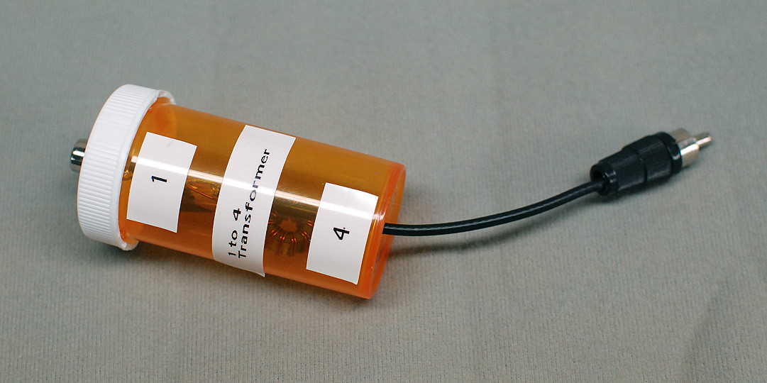
| 1:2 Voltage Step Up Transformer: In many cases, the output of the two transistor buffer amplifier is still too low. The output voltage can easily be doubled by running it through a 1 to 2 transmission line transformer. The transformer is mounted in a small pill bottle so it can be inserted or removed as needed. To learn more about the 1 to 2 transformer, go to the 1 to 2 Voltage Transformer Page. |
Click on the image for a larger view. |
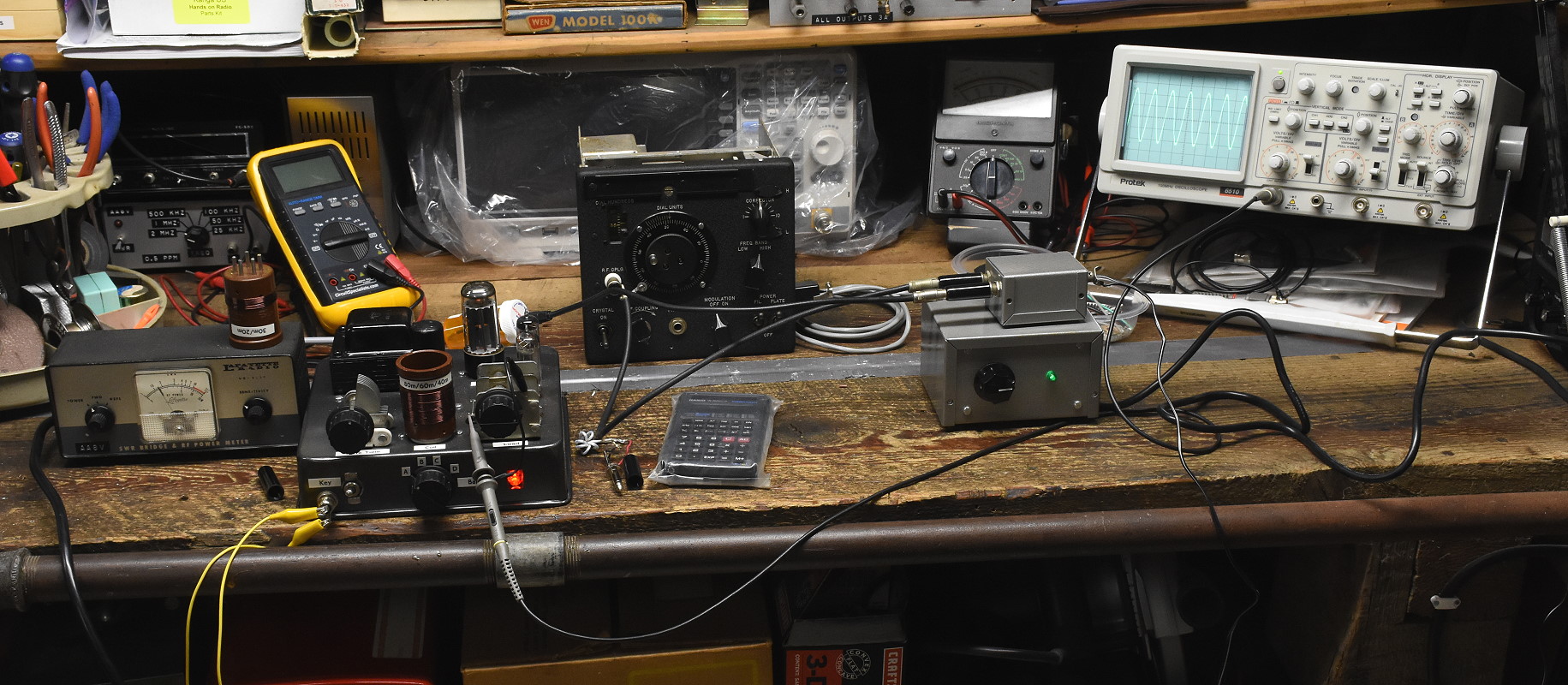
| Bench Testing The LM-13 VFO System: After the various individual components of the LM-13 VFO system were built, the entire system was tested on the workbench. In this picture the system is being used with my 6AG7 VFO amplifier to test performance on 80m. At extreme left is the photo is a Lafayette dummy load/wattmeter which shows an output of about 1.8 W. This is more than enough to drive the 6146 linear amplifier. The 6AG7 VFO amplifier is just to the right of the dummy load/wattmeter, and the output of the amplifier is connected to the oscilloscope, which shows a perfect sine wave output. The LM-13 is near the center of the photo. To the right of the LM-13 are the LM-13 power supply and the two transistor buffer amplifier, which is on top of the power supply.. The output of the buffer amplifier goes to a 1 to 2 voltage step up transformer, which can barely be seen (in an orange pill bottle) behind the 6AG7 VFO amplifier. |
 Click on the image for a larger view. Click here for a super detailed view. |
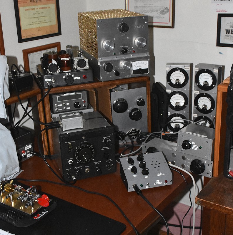
| LM-13 On The Air: As with any classic tube gear, the LM-13 should be warmed up for about 1/2 hour before use to allow it to stabilize. The LM-13 was never intended to be keyed, and there is an objectionable chirp/swoop if it is keyed. However, if the LM-13 oscillator is kept on during transmission and a later stage is keyed the result is beautiful keying. When activated for transmitting, there is a slight frequency "swoop" that lasts about one second after the oscillator is turned on. After that, the LM-13 very stable. When using the LM-13 on the air, one dot is sent to put the system in transmit mode, and after a one second pause transmission can begin. The signal is then rock solid throughout the transmission. In this picture, the LM-13 can be seen near the bottom left. The buffer amplifier is on top of the LM-13 and the power supply is on the right. The LM-13 drives the 6AG7 VFO amplifier and 6146 linear amplifier which are on the top of the shelf in the picture. The 6AG7 VFO amplifier is the only keyed stage. The 6146 amplifier is not keyed. |
 Click on the image for a larger view. Click here for a super detailed view. |
©Copyright Statement:
All images, designs, and materials on these web pages are the property of
Gregory P. Latta and are ©2018 by Gregory P. Latta. You may use them for
personal purposes and for educational purposes, but any commercial or other use
is strictly prohibited unless written permission is obtained from the author.
 Back to Dr. Greg Latta's
Electrical Engineering and Amateur Radio Pages
Back to Dr. Greg Latta's
Electrical Engineering and Amateur Radio Pages
 If you have any questions or
comments, you can send E-Mail to Dr. Greg Latta at
glatta@frostburg.edu
If you have any questions or
comments, you can send E-Mail to Dr. Greg Latta at
glatta@frostburg.edu