QSK-5 PIN Diode Switch Driver
| Main Page | Handshake Circuit |
| How PIN Diodes and PIN Diode Switches Work | QSK Indicator Modification |
| Building an Electronic Transmit/Receive Switch Using PIN Diode Switches | Hot Switching |
| PIN Switch Driver - Turning A PIN Diode Switch Off and On | Circuit Board And Parts Identification |
| T/R Input and Timing Circuits | Schematic Diagram and Circuit Descriptions |
Safety Note: Working on or testing the QSK-5 and associated circuitry may involve operating the amplifier containing the QSK-5 with the cover off. This is extremely dangerous since very high voltages are present when the amplifier is turned on, sometimes in close proximity to the QSK-5. If at all possible, do all work with the amplifier off and unplugged. The operator assumes all risk and liability in such matters! Never operate the amplifier with the cover off unless you are experienced with working around very high voltages!
| Circuit Requirements |
| Off Mode |
| On Mode |
| 2N6740 Data Sheet |
Circuit Requirements:
Turning a PIN Diode Switch off and on involves more than just opening or
closing a mechanical switch. To turn the diode switch on, a current of between
50mA and 500mA at about 12 volts maximum needs to be run through the switch in
the forward direction to fully turn on the PIN diodes. To turn the diode switch
off, several hundred volts at very little current needs to be applied to the
switch in the reverse direction to fully cut off the PIN diodes.
Though a mechanical relay could easily handle this situation, it defeats the
whole purpose of having a completely solid state, high speed, switching system.
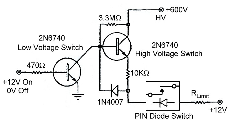
The switching can be achieved by using the PIN driver circuit shown below, which is used in the Ameritron QSK-5 system:
QSK-5 PIN Diode Switch Driver
The 2N6740 transistors can handle 650 volts and do not need heat sinks to handle the necessary current. The circuit needs a 12V supply and a 600V high voltage supply to operate properly. When the input to the circuit (the 470 ohm resistor) is connected to +12V, the PIN diode switch is turned on, and when the input is left open or grounded the PIN diode switch is turned off. Off Mode and On Mode are discussed more thoroughly below.
Off Mode:
When the input at the 470 ohm resistor is left open or grounded, no base
current flows in the low voltage switch, shutting the transistor off. Current
from the 600V supply flows through the 3M ohm resistor to the base of the high
voltage switch. This current can't pass through the low voltage switch since it
is turned off, and it can't pass through the 1N4007 diode since it is reverse
biased. The current therefore flows through the base of the high voltage
switch, turning it on:
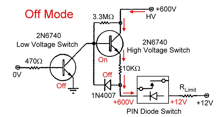
QSK-5 PIN Diode Switch Driver in OFF Mode
Once the high voltage switch is turned on, current flows from the 600V supply, through the transistor, and then through the 10k ohm resistor to the cathode side of the PIN diode switch. Since the anode side of the PIN diode switch is connected to 12V, 588V of reverse bias (600V - 12V) is applied to the diode switch, shutting it off.
On Mode:
If the 470 ohm resistor is connected to 12V, current flows through the base of
the low voltage switch, turning it on. This essentially grounds the base of the
high voltage switch, bypassing the current through the 3M ohm resistor to
ground. This turns the high voltage switch off.

QSK-5 PIN Diode Switch Driver in ON Mode
Current from the 12V supply then flows through the limiting resistor and the PIN diode switch, turning the diode switch on, and then continues through the 1N4007 diode and the low voltage switch to ground.
In practice the value of the limiting resistor must be chosen so that the proper forward current flows through the PIN diode switch. This resistor must be included, otherwise excessive current will flow, damaging the switching circuit, the PIN diode switch, or both. In the Ameritron QSK-5, the limiting resistor is 68 ohms for the receive switch and 10 ohms for the transmit switches, which are wired in series for DC.
Since no capacitors are included in the circuit to limit the response time, the circuit operates instantaneously (at least compared to CW keying speeds), with the state of the PIN diode switch following exactly the state of the input at the 470 ohm resistor.
2N6740 Data Sheet:
For everything you ever wanted to know about the 2N6740 transistor, you can
click here for a 2N6740 Data Sheet. This data
sheet is in .PDF format, so you must have
Adobe Reader installed
to read it.
 Back to Dr. Greg Latta's
Electrical Engineering and Amateur Radio Pages
Back to Dr. Greg Latta's
Electrical Engineering and Amateur Radio Pages
 If you have any questions or
comments, you can send E-Mail to Dr. Greg Latta at
glatta@frostburg.edu
If you have any questions or
comments, you can send E-Mail to Dr. Greg Latta at
glatta@frostburg.edu