QSK Indicator Circuit Using the Existing Closed Loop Output
| Main Page | Handshake Circuit |
| How PIN Diodes and PIN Diode Switches Work | QSK Indicator Modification |
| Building an Electronic Transmit/Receive Switch Using PIN Diode Switches | Hot Switching |
| PIN Switch Driver - Turning A PIN Diode Switch Off and On | Circuit Board And Parts Identification |
| T/R Input and Timing Circuits | Schematic Diagram and Circuit Descriptions |
Safety Note: Working on or testing the QSK-5 and associated circuitry may involve operating the amplifier containing the QSK-5 with the cover off. This is extremely dangerous since very high voltages are present when the amplifier is turned on, sometimes in close proximity to the QSK-5. If at all possible, do all work with the amplifier off and unplugged. The operator assumes all risk and liability in such matters! Never operate the amplifier with the cover off unless you are experienced with working around very high voltages!
| Introduction |
| Circuit Description When Closed Loop QSK Is NOT Used |
| Circuit Description When Closed Loop
QSK IS Used Recommended Method |
| Operating With The QSK Indicator |
Introduction:
The QSK-5 and QSK-5 PC are great units. They
are well engineered, reasonably priced, and do a great job when installed and
operated correctly. The only thing lacking with these units is a way of knowing
visually when the unit is in transmit mode. Without such a visual
indicator, the operator cannot tell if the unit is functioning correctly
without sending RF through the unit, which can potentially blow the fuse lamps
on the circuit board.
For example, I have my QSK-5PC mounted in my Ameritron AL-572 amplifier, and I use the amplifier with three different transmitters/transceivers. I have a switch in the T/R line to switch the QSK-5 T/R input to the correct transmitter. If I switch to the wrong transmitter and transmit, I blow the fuse lamps on the QSK-5PC. With a QSK indicator, I can transmit with the amplifier in standby mode, without sending any RF through the QSK-5. If the QSK indicator lights, I know it is OK to switch to operate mode. If the QSK indicator fails to light, I know I have a problem.
Circuit Description When Closed Loop QSK
Is NOT Used:
Fortunately, it very easy to add a visual QSK indicator to the QSK-5. The QSK-5
contains a handshake circuit that is
for use in closed loop QSK systems. The handshake circuit turns on a transistor
connected to pin K that indicates to the transceiver that the QSK-5 is truly in
transmit mode. If you never plan to use the closed loop QSK system, you can
simply use the closed loop QSK output at pin K to control a QSK indicator LED,
as shown in the schematic diagram below:
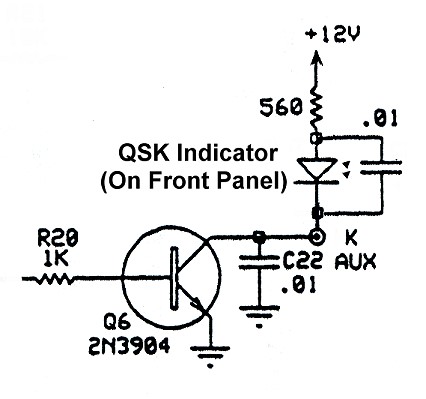
QSK Indicator Circuit Using the Existing Closed Loop Output
The LED is mounted on the front panel. The wires running to the LED should be kept well away from any high voltage cables or components and should be as short as possible. The 0.01 uf capacitor should be mounted as close to the QSK-5 circuit board as possible so that any stray RF picked up by the wires running to the LED is bypassed before it has a chance to get into the QSK-5 circuit board. (Though I didn't use one, a small ferrite bead over the wires running to the LED wouldn't hurt.) The 560 ohm resistor controls the brightness of the LED. Decreasing the value will brighten the LED, and increasing the value will dim the LED.
Circuit Description When Closed Loop QSK IS
Used: (Recommended Method)
(I recommend this method even if you don't plan to use the full loop
QSK since it is easy to do and leaves the original loop output unaltered.)
If you plan to use the closed loop QSK system, it is very easy to add another
2N3904 transistor to drive an indicator LED. The LM-324 op-amp in the handshake
circuit has more than enough output to drive the additional transistor. By the
way, don't try to use the same transistor to drive both the LED and the loop
return! Doing so could damage the loop return input to the transceiver. The
complete circuit is shown below:
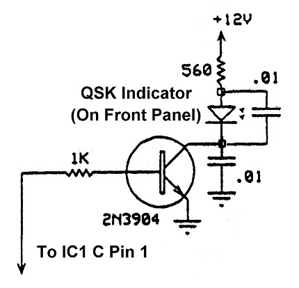
Stand Alone QSK Indicator Circuit (Recommended)
Mount the transistor and other components on a small piece of vector board or circuit board. You can then use a drop of hot melt glue to glue the indicator board to the top of the LM-324 op-amp, as shown in the photo below:
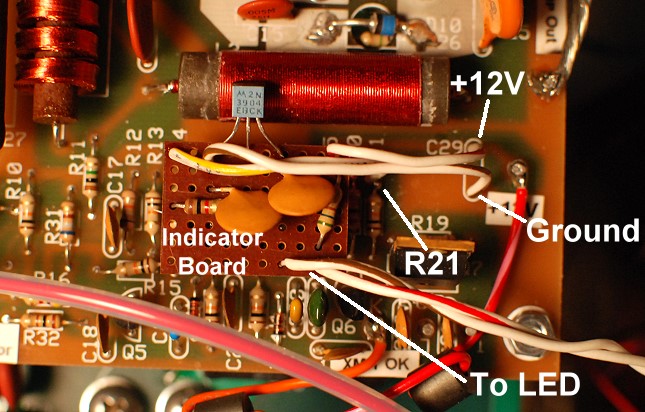
Stand Alone QSK Indicator Circuit Mounted on Top of the LM-324 Op-Amp
Connections for +12V and ground can conveniently be made to the unused holes for C29. The top hole (red-white wire) is for +12V, and the bottom hole (brown-white wire) is for ground. The connection to pin 1 of IC1 can be made by soldering a wire (yellow-white) around the top end of resistor R21 (Br-Bl-Or) which is connected to pin 1 of IC1. See the photo above. The LED is mounted on the front panel. The wires running to the LED (red-white and brown-white) should be kept well away from any high voltage cables or components and should be as short as possible. Though I didn't use one, a small ferrite bead over the wires running to the LED wouldn't hurt.
Operating With The QSK Indicator:
My QSK-5 is installed in an Ameritron AL-572 amplifier. When I wish to use the
amplifier, I always make sure that the amplifier is in STANDBY mode before I
turn it on. This bypasses the amplifier, including the QSK-5, and routes the
transceiver signal directly to the antenna. I then key the transceiver and make
sure that the QSK indicator lights up. If the QSK indicator does NOT light
when the transceiver is keyed and the amplifier is in STANDBY mode, something
is wrong and you should NOT switch the amplifier to OPERATE/TRANSMIT mode!
If the QSK light does come on when you key the transceiver, then it is safe to
place the amplifier into OPERATE/TRANSMIT mode. The QSK indicator should light
every time the transceiver is keyed. In a full QSK system the indicator will
come on and off with your individual dots and dashes. If at any time the
indicator light fails to come on when the transceiver is keyed, stop sending
immediately, switch the amplifier to STANDBY mode, and find out what the
problem is.
Operating With The QSK Indicator Can Be
Summarized With One Simple Rule:
If the QSK indicator doesn't light when the amplifier is in
STANDBY mode and the transceiver is keyed, then don't switch the
amplifier to OPERATE/TRANSMIT mode!
 Back to Dr. Greg Latta's
Electrical Engineering and Amateur Radio Pages
Back to Dr. Greg Latta's
Electrical Engineering and Amateur Radio Pages
 If you have any questions or
comments, you can send E-Mail to Dr. Greg Latta at
glatta@frostburg.edu
If you have any questions or
comments, you can send E-Mail to Dr. Greg Latta at
glatta@frostburg.edu