
Ameritron QSK-5PC Schematic with AA8V QSK Indicator Circuit
Ameritron QSK-5PC Schematic with AA8V QSK Indicator Circuit
| Main Page | Handshake Circuit |
| How PIN Diodes and PIN Diode Switches Work | QSK Indicator Modification |
| Building an Electronic Transmit/Receive Switch Using PIN Diode Switches | Hot Switching |
| PIN Switch Driver - Turning A PIN Diode Switch Off And On | Circuit Board Photos And Parts Identification |
| T/R Input and Timing Circuits | Schematic Diagram and Circuit Descriptions |
Safety Note: Working on or testing the QSK-5 and associated circuitry may involve operating the amplifier containing the QSK-5 with the cover off. This is extremely dangerous since very high voltages are present when the amplifier is turned on, sometimes in close proximity to the QSK-5. If at all possible, do all work with the amplifier off and unplugged. The operator assumes all risk and liability in such matters! Never operate the amplifier with the cover off unless you are experienced with working around very high voltages!
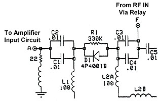
Transmit Diode - Amplifier Input Switch: A single M/A-COM type MA4P4001B PIN diode is used in the QSK-5 amplifier input switch. This is the same type of diode used in the amplifier output switch. The diode is mounted underneath the large RF choke on the top left side of the circuit board. A 330 kohm equalizing resistor is connected across the diode, and, for DC, this diode is connected in series with the amplifier output diodes, and is controlled by the transmit switch driver. For more information on how the amplifier input switch functions, you can go to the How PIN Diodes and PIN Diode Switches Work page. For all the information you ever wanted to know about the MA4P4001B diode, click here for the MA4P4001B data sheet from M/A-COM. This data sheet is in .PDF format, so you must have Adobe Reader installed to read it. |
 Click for a Circuit Board View |
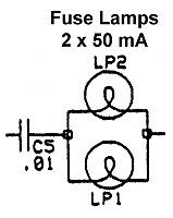
Fuse Lamps: The fuse lamps are located on the top of the circuit board to the left. These light if the current through the receive diodes is excessive. When the bulbs light up, their resistance increases, protecting the expensive diodes. If the current becomes too much, the lamps burn out, just like a fuse. If this happens, you cannot receive while using the QSK-5. Do not bypass the bulbs or try to use a fuse in their place. Unlike a fuse, the resistance of the bulb increases as the bulb lights up, further protecting the receive diodes. The lamps are replaced by unsoldering them and installing new ones. Any 50 mA 12V or 15V bulb can be used. You can purchase replacement lamps from Ameritron or find them at Radio Shack, if you are lucky. It pays to keep a couple of extra bulbs on hand. |
 Click for a Circuit Board View |
Receive Diodes - Receive Switch: The receive PIN diodes used in the QSK-5 are M/A-COM type MA4PH301. These are the small blue units in this photo. Ameritron decided to double the number of diodes used in the PIN diode receive switch by replacing each original diode with two diodes in series, with a 1 Mohm equalizing resistor across each one. This gives a total of eight diodes is series for the PIN diode receive switch For more information on how the receive switch functions, you can go to the How PIN Diodes and PIN Diode Switches Work page. For all the information you ever wanted to know about the MA4PH301 diode, click here for the MA4PH301 data sheet from M/A-COM. This data sheet is in .PDF format, so you must have Adobe Reader installed to read it. |
 Click for a Circuit Board View |
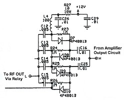
Transmit Diodes - Amplifier Output Switch: The PIN diodes used in the QSK-5 amplifier output switch are M/A-COM type MA4P4001B. These are the large blue units in this photograph. Four diodes are used for the amplifier output switch. The diodes are wired in parallel for RF and in series for DC. A 1 Mohm equalizing resistor is placed across each diode. For more information on how the amplifier output switch functions, you can go to the How PIN Diodes and PIN Diode Switches Work page. For more information on the MA4P4001B diode, click here for the MA4P4001B data sheet from M/A-COM. This data sheet is in .PDF format, so you must have Adobe Reader installed to read it. |
 Click for a Circuit Board View |
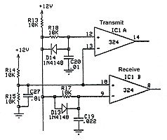
Timing Circuits: The timing circuits are located at the bottom right hand corner of the QSK-5 circuit board, as seen in this photo. You can learn more about how the timing circuits work by going to the T/R Input and Timing Circuits page. |
 Click for a Circuit Board View |
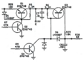
Switching Transistors: The PIN diode switching transistors are located on the circuit board where the high voltage lead connects to the circuit board at point E. The driver utilizes four 2N6740 high voltage power transistors to turn the PIN diode switches off and on. To operate properly, the switch driver needs about 600V DC in addition to the usual 12V DC that powers the rest of the QSK-5. The 600V connects to the QSK-5 at point E on the circuit board, in the middle of the four 2N6740 transistors. For more information on the operation of the switching transistors, go to the PIN Switch Driver page. For more information on the 2N6740 transistors, click here for the 2N6740 data sheet. This data sheet is in .PDF format, so you must have Adobe Reader installed to read it. |
 Click for a Circuit Board View |
Handshake Circuit: The handshake circuit is located at the bottom right hand corner of the QSK-5 circuit board, as seen in this photo. For more information on how the handshake circuit operates, go to the Handshake Circuit page. |
 Click for a Circuit Board View |
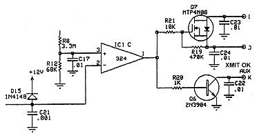
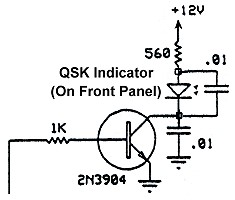
QSK Indicator Circuit: The QSK indicator circuit is on the small vectorboard mounted on top of the LM-324 op-amp at the bottom right hand corner of the QSK-5 circuit board, as seen in this photo. This is an add-on circuit of my design which lights an LED on the amplifier front panel whenever the QSK-5 is placed in transmit mode. You can read all about the indicator circuit by going to the QSK Indicator Modification page. |
 Click for a Circuit Board View |
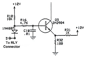
T/R Input Circuit: The T/R input circuit is located at the bottom of the board by pin D. The 1N4007 diode connected to pin D is to protect the QSK-5 in case a signal of the wrong polarity is connected to the T/R input of the amplifier. If connected to the wrong polarity, the diode simply prevents any current from flowing through it into the QSK-5. To learn more about how the T/R input circuit functions, you can go to the T/R Input and Timing Circuits page.. |
 Click for a Circuit Board View |
 Back to Dr. Greg Latta's
Electrical Engineering and Amateur Radio Pages
Back to Dr. Greg Latta's
Electrical Engineering and Amateur Radio Pages
 If you have any questions or
comments, you can send E-Mail to Dr. Greg Latta at
glatta@frostburg.edu
If you have any questions or
comments, you can send E-Mail to Dr. Greg Latta at
glatta@frostburg.edu