
Click here for a higher resolution (larger) schematic.
Introduction:
Trying to figure out exactly how the various switches in the Viking Ranger work
can be very difficult. This is due to partly to the lack of clarity in many of
the schematic diagrams. I was able to obtain a very clear schematic diagram
from a Johnson Ranger catalog page and from that I was able to work out how the
various switches operate.
The operate switch has two sections, one that takes care of AC power and other
control functions and another that takes care of
switching B+. One part of the
AC power/control section switches AC on and off to the power transformer and
antenna change over relay connector. Another part of the switch controls the
key line, the multiplier cathode, and the power amplifier screen grid.
The operation of the switch can best be summarized in the table below:
| Switch Position | Power Transformer |
Antenna Change Over Relay | Multiplier Cathode | Key | PA Screen Grid |
| Off | Off | Off | Open | Grounded | Grounded |
| Tune | On | Off | Grounded | Grounded | Grounded |
| Phone | On | On | Key | Multiplier Cathode | Ungrounded |
| Standby | On | Off | Open | Open | Grounded |
| CW | On | On | Grounded | Open | Ungrounded |
The effect of the switch in each position can be summarized
in the following table:
| Switch Position | Effect |
| Off | All transmitter circuits turned off. |
| Tune | Power amplifier and modulator disabled. Transmit light off. |
| Phone | Power amplifier enabled. Modulator enabled. Modulated High B+ fed to power amplifier. Transmit light turned on. |
| Standby | Power amplifier and modulator are disabled. Transmit light off. |
| CW | Power amplifier enabled. Modulator disabled. Unmodulated B+ fed to power amplifier. Transmit light turned on. |
Operate Switch - AC
Power/Control Section
Click On A Section of the Schematic
Below for Information on That Part of the Circuit:
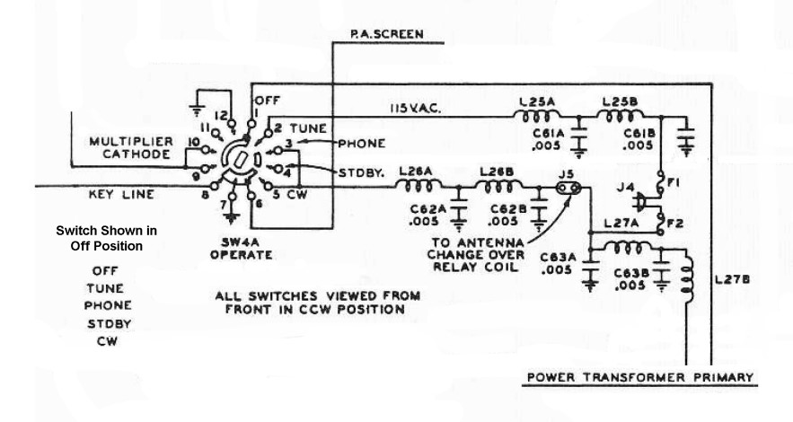
| Multiplier Cathode |
| Key Line |
| P.A. Screen Grid |
| Power Transformer Primary |
| Power Cord And Fuses |
| Antenna Change Over Relay Connector |
| Double L Network |
| Key Line: The key line is connected to the operate switch so that it can be used to control the multiplier cathode in PHONE mode. In modes other than PHONE, the key is disconnected from the multiplier cathode. In PHONE mode the multiplier cathode is connected to ground through the key, so that the multiplier is controlled by the key. |
| Power Transformer Primary: 120V is applied to the power transformer primary in all positions of the operate switch except in the off position. |
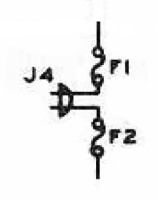
| Power Cord and Fuses: Two fuses are used in the Johnson Viking Ranger. A 3A Fusetron slow blow fuse (F1) and and a 5A fast blow fuse (F2) are mounted at the end of the line cord.. The two fuses together guarantee that a fuse will blow under any undesirable condition. In restored Ranger transmitters, it is customary (and safer) to replace the original line cord with a modern grounded line cord and a single fuse. A single 5A fast blow fuse is recommended in a restored Ranger. |
 |
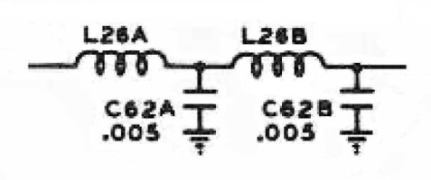
| Double L Network: To prevent any RF from entering or exiting via power cord or antenna change over relay connector double L networks are installed on all of the leads. These consist of two RF chokes, which block any RF, and two capacitors that short any remaining RF to ground. Single L networks are used extensively throughout the Ranger to prevent any RF from getting where it shouldn't, but double L networks are only used on the power cord and antenna change over leads. |
 |
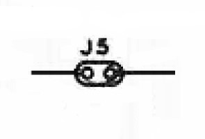
| Antenna Change Over Relay Connector: A switched connector is supplied on the back of the Johnson Ranger to power an external T/R antenna relay. 120V is applied to the connector only when the operate switch is in the PHONE or CW positions. Connections to J5 are filtered by double L networks. |
 |
 Back to Dr.
Greg Latta's Electrical Engineering and Amateur Radio Pages
Back to Dr.
Greg Latta's Electrical Engineering and Amateur Radio Pages
 If you have any questions or
comments, you can send E-Mail to Dr. Greg Latta at
glatta@frostburg.edu
If you have any questions or
comments, you can send E-Mail to Dr. Greg Latta at
glatta@frostburg.edu