Click here for a higher resolution (larger) schematic.
Introduction:
Trying to figure out exactly how the various switches in the Viking Ranger work
can be very difficult. This is due to partly to the lack of clarity in many of
the schematic diagrams. I was able to obtain a very clear schematic diagram
from a Johnson Ranger catalog page and from that I was able to work out how the
various switches operate.
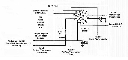
The operate switch has two sections, one that takes care of
AC power and other control
functions and another that takes care of switching B+. The B+ section
switches the high B+, tapped high B+ (from R35), and 6.3V AC in and out of
various circuits. The operation of the switch can best be summarized in the
table below:
| Switch Position | PA Plate | Modulator Screens | I4 |
| Off | Off | Off | 0V AC - Off |
| Tune | High B+ Through Shunt SH4 And Modulation Transformer Secondary |
Off | Off |
| Phone | Modulated High B+ Through Shunt SH4 And Modulation Transformer Secondary |
Tapped High B+ | 6.3V AC - On |
| Standby | High B+ Through Shunt SH4 And Modulation Transformer Secondary |
Off | 0V AC - Off |
| CW | High B+ Through Shunt SH4 Modulation Transformer Bypassed |
Off | 6.3V AC - On |
The effect of the operate switch in each position can be
summarized in the following table:
| Switch Position | Effect |
| Off | All transmitter circuits turned off. |
| Tune | Power amplifier and modulator disabled. Transmit light off. |
| Phone | Power amplifier enabled. Modulator enabled. Modulated High B+ fed to power amplifier. Transmit light turned on. |
| Standby | Power amplifier and modulator are disabled. Transmit light off. |
| CW | Power amplifier enabled. Modulator disabled. Unmodulated B+ fed to power amplifier. Transmit light turned on. |
Operate Switch - B+
Section
Click On A Section of the Schematic
Below for Information on That Part of the Circuit:

| High B+ From Power Supply: High B+ from the power supply is supplied directly to the primary of the modulation transformer and the top end of plate current shunt SH4 at all times. |
| Tapped High B+ From R35: Resistor R35 acts as a bleeder resistor for the high B+ power supply and also functions as an adjustable voltage divider to supply the proper voltage to the modulator and clamper tube screens. The tapped high B+ is always applied to the clamper tube screen, but is only applied to the modulator screens when the operate switch is placed in the PHONE position. Keeping the tapped B+ off of the modulator screens except in the PHONE position effectively disables the modulator in all modes other than PHONE. |
| 6.3V AC From Power Supply: 6.3V AC from the power supply is applied to the Operate switch. In the PHONE and CW modes the Operate switch sends this to lamp I4, the transmit light on the front panel, turning on the lamp. The lamp is otherwise off. |
| High B+ To Modulation Transformer Primary: High B+ is applied to the modulation transformer primary (and thus the modulator tube plates) at all times. However, unless the switch is in the PHONE mode, the screens of the modulator tubes are disconnected, disabling the modulator. |
| High B+ To Modulation Transformer Secondary: High B+ via shunt SH4 is applied to one side of the modulation transformer secondary at all times. However, high B+ flows through the secondary only in the PHONE mode. In PHONE mode, the high B+ passes through shunt SH4, through the modulation transformer secondary, and then to the power amplifier plate. In CW mode, high B+ is passed through shunt SH4 and then directly to the power amplifier plate through pins 11 and 12 of the Operate switch. |
| Tapped High B+ To Modulator Screens: Tapped B+ from R35 is only applied to the modulator screen grids when the Operate switch is in the PHONE position. In other positions the screens are left open, disabling the modulator. |
| Modulated High B+ From Modulation Transformer Secondary: Modulated high B+ is applied to the power amplifier only in the PHONE position of the Operate switch. In CW mode the modulation transformer is bypassed, and the high B+ passes directly to the power amplifier. In other positions, B+ is not applied to the power amplifier, or the screen of the power amplifier is grounded to disable it, as in the STANDBY position. |
| To PA Plate: High B+ or modulated high B+ is applied to the plate of the RF power amplifier at all times. In the TUNE and STANDBY modes the power amplifier is disabled by grounding the power amplifier screen grid via the other section of the Operate switch. In the CW mode tabs 11 and 12 on the Operate switch bypass he modulation transformer secondary so that high B+ is applied directly to the power amplifier plate from the high B+ power supply. |
| Transmit Light: The Transmit Light is activated in the PHONE and CW positions of the Operate switch. It is turned on by the Operate switch when the final amplifier is enabled. |
 |
| Tapped High B+ Bypass Capacitor: C73 is connected so that any stray RF that finds its way onto the tapped high B+ line is shorted to ground. |
 |
| Plate Current Meter Shunt: The plate and screen current for the final amplifier and clamper tube plate current flows through plate current metering resistor SH4. The voltage drop is read by the front panel meter. Because the clamper tube current flows through shunt SH4, the current indicated is not the true plate current. However, when transmitting, the clamper tube is shut off, so that the current indicated while transmitting is the sum of the power amplifier plate and screen currents, which is an excellent indicator of amplifier performance and an accurate indicator of proper amplifier tuning. |
 |
 Back to Dr.
Greg Latta's Electrical Engineering and Amateur Radio Pages
Back to Dr.
Greg Latta's Electrical Engineering and Amateur Radio Pages
 If you have any questions or
comments, you can send E-Mail to Dr. Greg Latta at
glatta@frostburg.edu
If you have any questions or
comments, you can send E-Mail to Dr. Greg Latta at
glatta@frostburg.edu