| Introduction and
Front and Side View Photos |
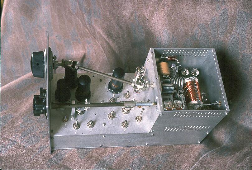
Power
Supply, Interior, and Rear View Photos |
| Schematic Diagrams and Circuit
Descriptions |
Special
Features |
| Block
Diagram |
Chassis Layout |
General Information: The Wingfoot VFO Exciter is a CW transmitter of the frequency multiplying type. The VFO operates on 3500kHz and is run straight through on 80m, doubled for the 40m band, and quadrupled for the 20m band. For 30m band the VFO operates on 3367kHz and is tripled. A final amplifier featuring variable regulated screen voltage operates straight through on all bands with an output continuously variable from 3W to 27W. A clamper tube protects the final amplifier in case of loss of bias for any reason. The transmitter features differential or timed sequence keying to provide clean, chirp free keying.
Block Diagram
Click On A Section of the Block Diagram
Below for Information on That Part of the Circuit:

| Oscillator |
| Cathode Follower |
| 1st. Buffer/Multiplier |
| 2nd. Buffer/Multiplier |
| Final Amplifier |
| Clamper/Screen Regulator |
| Differential Keying |
 Back to Dr. Greg Latta's
Electrical Engineering and Amateur Radio Pages
Back to Dr. Greg Latta's
Electrical Engineering and Amateur Radio Pages
 If you have any questions or
comments, you can send E-Mail to Dr. Greg Latta at
glatta@frostburg.edu
If you have any questions or
comments, you can send E-Mail to Dr. Greg Latta at
glatta@frostburg.edu