| Main Page and Front and Side Views | Tank Coil Information |
| Interior and Back Views | Typical Operating Conditions |
| Circuit Description and Schematic Diagram | Power Supply Photos |
| 813 Tube Information | Power Supply Circuit Description and Schematic Diagram |
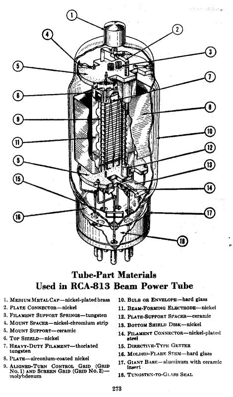
The 813 beam power tube was very popular with amateur radio operators following WW II. The tube remained a staple of amateur radio until single sideband became a popular operating mode in the late 1950's and early 1960's. Featuring a graphite plate with an ICAS dissipation rating of 125 watts the tube was very economical and a pair could provide legal limit operation (1 kilowatt input) on CW or AM. Later tubes manufactured by RCA and Amperex featured an improved plate made of zirconium-coated nickel.
With a thoriated tungsten filament, the 813 was introduced by RCA in 1938. News of the new transmitting tube first reached the amateur community in the November, 1938 issue of QST magazine. The 813 followed on the heels of the famous 6L6 beam power tube, which was the first power tube to use the electron beam principle.
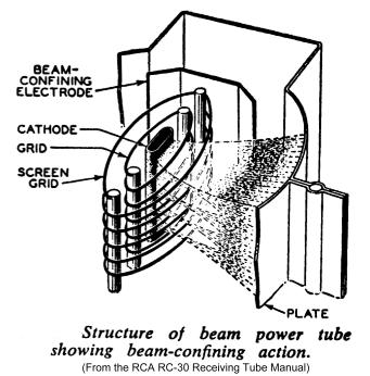
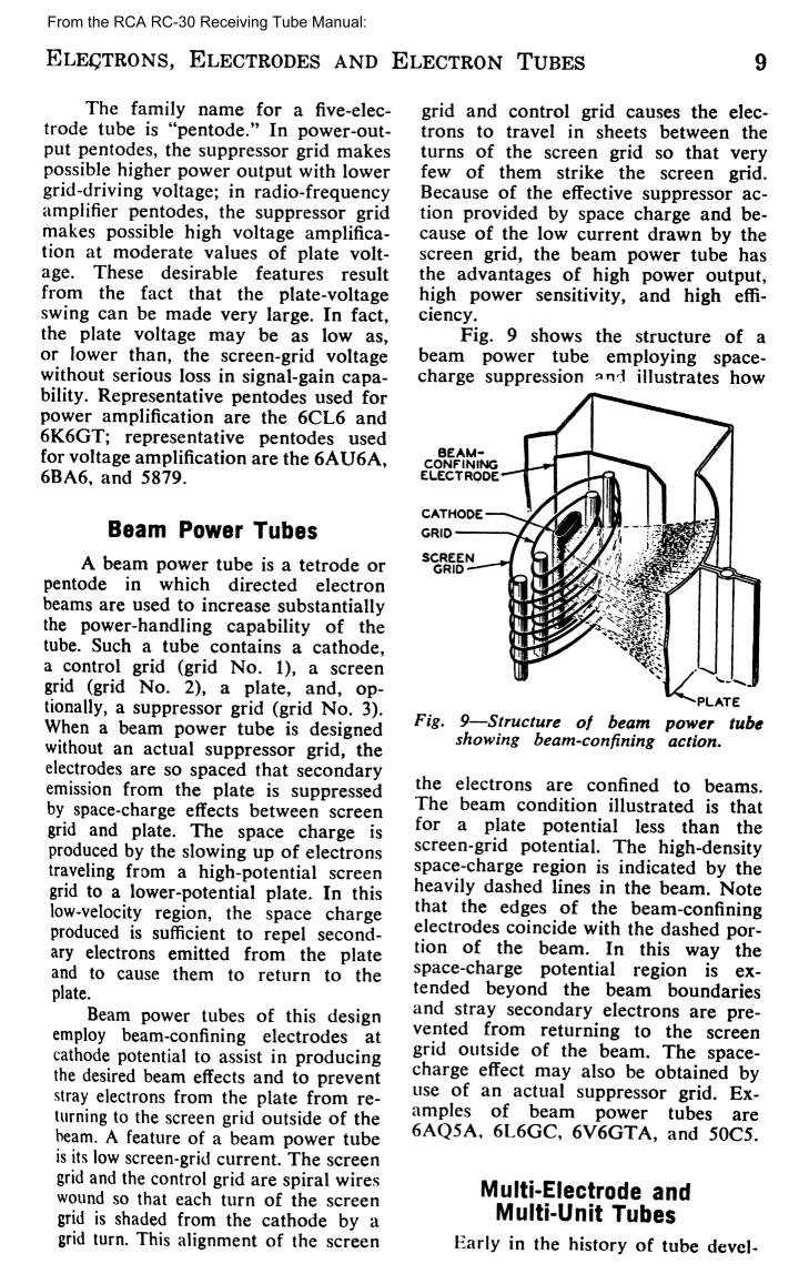
The 6L6 was released in 1936 and was first announced on page 50 of the May, 1936 issue of QST magazine. The 6L6 revolutionized power tube design by forming the electrons into beams and using aligned control and screen grids to limit grid and screen currents. Forming the electrons into beams increased the space charge near the plate, which then repelled secondary electrons back to the plate, eliminating the need for a surpressor grid. See the digram below. Other beam tubes eventually followed, including the 813, 2E26, 6146, 5763, and 6V6.
Although a pair of 813s was perfect for legal limit operation on CW and AM, the tube was unable to supply the high peak inputs permitted in single sideband operation, and thus the popularity of the tube dropped as SSB became the preferred mode over AM.
 Back to Dr.
Greg Latta's Electrical Engineering and Amateur Radio Pages
Back to Dr.
Greg Latta's Electrical Engineering and Amateur Radio Pages
 If you have any questions or
comments, you can send E-Mail to Dr. Greg Latta at
glatta@frostburg.edu
If you have any questions or
comments, you can send E-Mail to Dr. Greg Latta at
glatta@frostburg.edu