
Introduction and Historical Background:
After I completed the 6CL6 One Tube
Transmitter, I decided that I wanted to build a matching amplifier. Though
the transmitter was mostly my work, a lot of the work was that of
Jim Trutko, W8EXI, and I wanted to
build a piece of equipment that was 100% my work. The
transmitter had an output of 1.25-5
watts, which was fine when band conditions were very good, but not enough when
band conditions were poor. A homebrew amplifier with 50-60 watts of output
would make a big improvement on the air, and seemed like the ideal follow up
project.
I had to do a lot of research to find a design for the amplifier. I hunted through back issues of QST (on CD-ROM) and through my collection of ARRL handbooks. I found the plans for a beautiful amplifier on page 186 of the 1965 ARRL handbook titled "A 90 Watt All-Purpose Amplifier". This design used a single 6146 tube and could be run as a linear amplifier on SSB or as a class C amplifier on CW. This was ideal for my purposes, and it looked like I could scrounge up all of the necessary parts, except for the grid input circuit, which was a commercially available (in 1965) sub-assembly. Though easy enough to buy in 1965, the chances of finding such a unit several decades years later were about zero. I would have to design my own input circuit or borrow one from another design.
After doing some more research, I found a design for a 200 watt amplifier in the 1967 ARRL handbook that used a pair of 6146 tubes. The input circuit for this amplifier used a B & K "Air Dux" inductor that I just happened to have on hand in my junk box! Though the input impedance for a single 6146 would be twice that of a pair, I figured that the input circuit would still work, especially since I would have a lot of extra drive available from the 6CL6 transmitter.
The resulting design is thus the 1965 handbook design with the input circuit from the 1967 design. For the power supply I used the same design as the 1965 amplifier, but with solid state, rather than tube, rectifiers.
In these pages, which will be in a constant state of improvement, are pictures of the amplifier and its various parts. Eventually, circuit diagrams, circuit explanations, and the history and details of the design and construction will be included. Please check back from time to time.
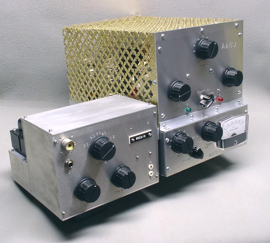
| 6CL6 One-Tube Transmitter and 6146B Amplifier: In this photo you can see the 6CL6 transmitter on the left and the finished amplifier on the right. The same chassis construction used on the transmitter was also used on the amplifier. Matching knobs were purchased from Radio Shack. The gold cage on the transmitter was made from decorative sheeting left over from a kitchen remodeling project. The cage protects the operator from high voltage and also keeps RF inside the transmitter. |
 Click on the image for a larger view. Click here for a super detailed view. |
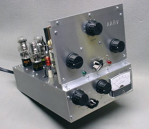
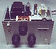
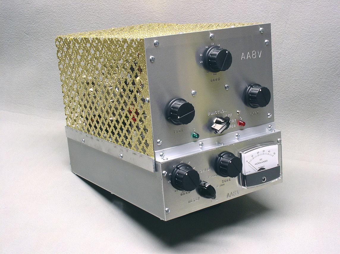
| Front View: In this view of the amplifier the knob at the top of the upper panel is the bandswitch for the plate tank circuit and the left knob on the bottom panel is the band switch for the grid circuit. Changing bands requires that both switches to be set to the same band. Using separate band switches makes band changes a little more awkward, but it simplifies construction and provides much better isolation between the input and output circuits, yielding an amplifier that is more stable.. The other two large knobs on the upper panel are the plate tuning (left) and plate loading (right) capacitors, and the large knob next to the meter on the bottom panel is the grid tuning/drive capacitor. |
Click on the image for a larger view. Click here for a super detailed view. |
| Front View With High Voltage Cage Removed - Left Side:
In this view with the the high voltage cage removed the three voltage regulator tubes and plate RF choke can be seen towards the back of the amplifier The small switch on the upper panel is the power/standby/operate switch. In standby mode, both plate and filament supplies are on, the tube is biased to cut-off, and the input is directly routed to the output, bypassing the amplifier. In operate mode, cut-off bias is removed and the amplifier is switched into the circuit. (The amplifier can also be remotely switched from standby to operate.) The small knob on the bottom panel is the meter switch. The meter can be switched to read plate current (250ma full scale), screen current (25ma full scale), or grid current (5ma full scale). |
 Click on the image for a larger view. Click here for a super detailed view. |
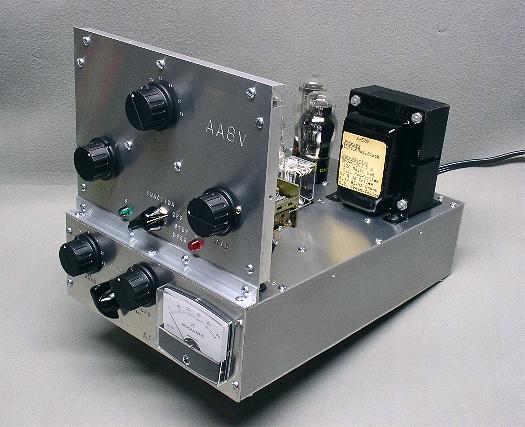
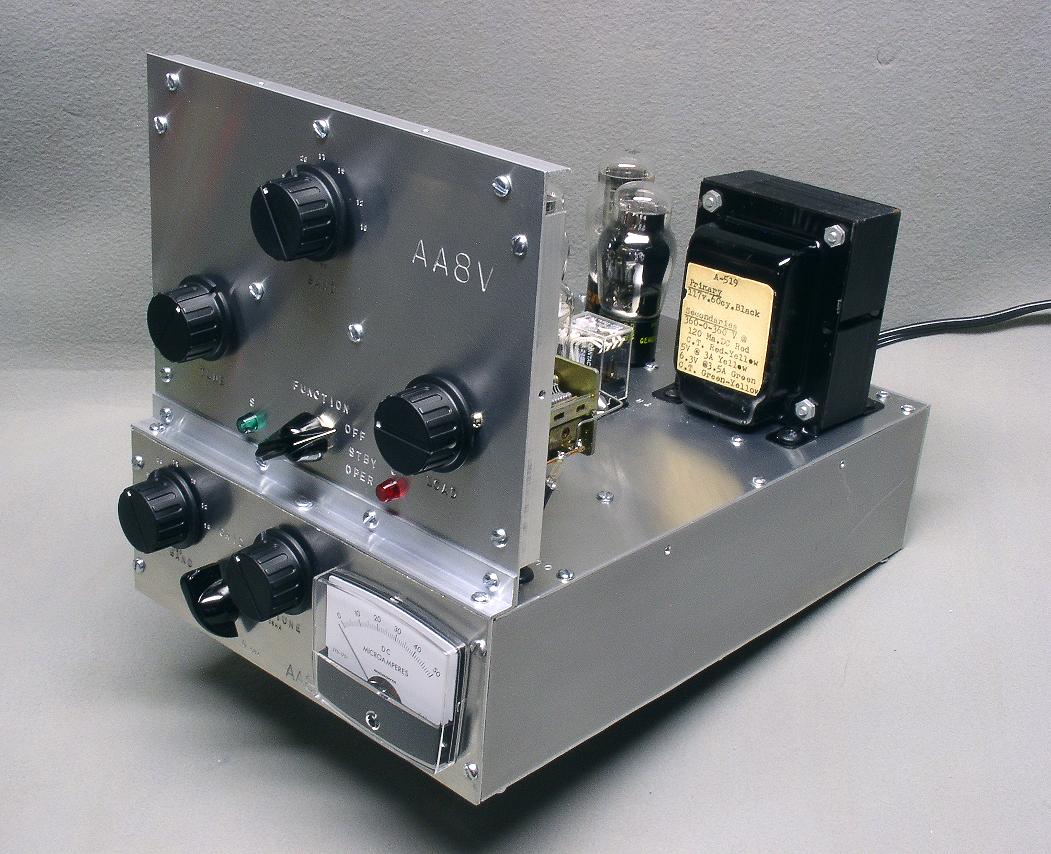
| Front View With High Voltage Cage Removed - Right Side:
This view from the other side of the amplifier nicely shows the power transformer. The transformer was in an old piece of equipment being discarded by Frostburg State University, where I am a professor, and I saved it from the landfill. The transformer secondaries (which can be read in the super detailed photo) are rated at 720V center tapped at 120ma, 6.3V center tapped at 3.5A, and 5V at 3A. (The 5V secondary was not used in the amplifier). |
 Click on the image for a larger view. Click here for a super detailed view. |
| Side View With High Voltage Cage Removed: The power supply components of the amplifier are mounted at the rear of the chassis as can be seen in this photo. Three voltage regulator tubes are used in the amplifier, one for the bias supply and two for the screen supply. These can be seen next to the power transformer at the rear of the chassis. The 6146B tube, neutralizing capacitor, and plate RF choke can be seen in the middle of the chassis, and the plate tank circuit components can be seen mounted on the front panel on the right. |
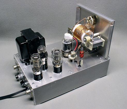 Click on the image for a larger view. Click here for a super detailed view. |
| Rear View With High Voltage Cage Removed: All connections to the amplifier are made on the rear panel. The amplifier output is the SO-239 connector on the left, and the input is on the right. The large connector in the middle is the control connector. The amplifier can be remotely switched from standby to operate mode by making the appropriate connections to the control connector. The small knob on the back panel is used to set the bias on the amplifier. (The bias is set for an idling plate current of 15ma). |
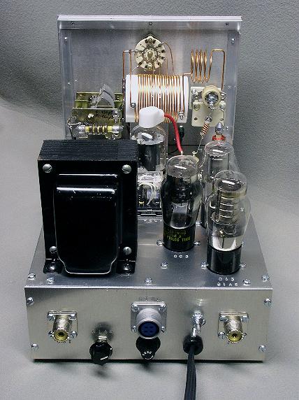 Click on the image for a larger view. Click here for a super detailed view. |
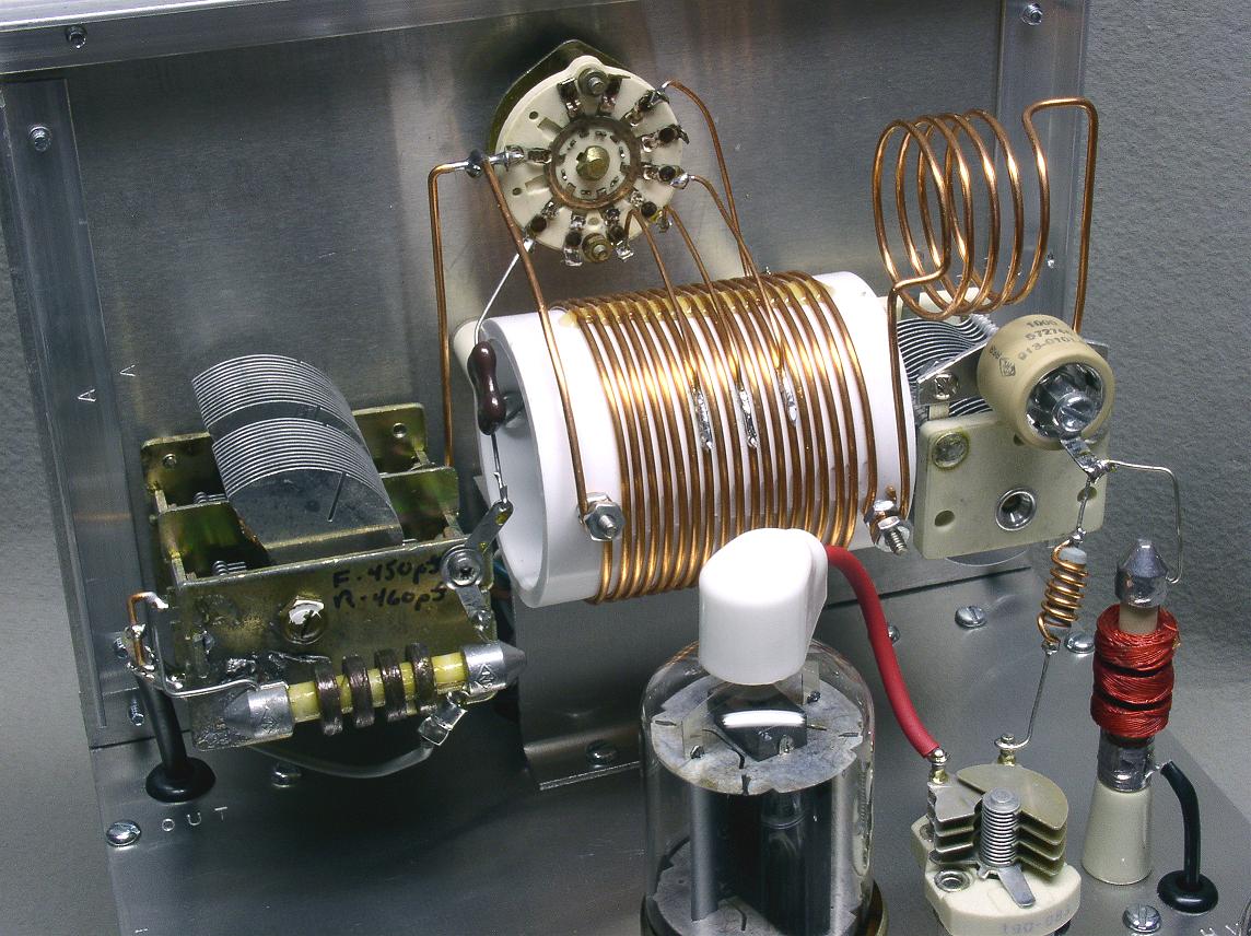
| Plate Tank Circuit: The plate tank circuit is mounted on the back of the front panel. The loading capacitor is on the left, the tank coil is in the middle, and plate tuning capacitor is on the right. The small coil by itself on the right is the 10 meter coil. The plate bandswitch is in the middle, above the tank coil. A Centralab "doorknob" capacitor couples the plate tank circuit to the plate of the tube. The small variable capacitor in the bottom of the picture is the neutralizing capacitor, and the red coil on the right is the plate RF choke. |
 Click on the image for a larger view. Click here for a super detailed view. |
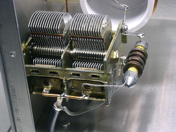
| Plate Loading Capacitor: The plate loading capacitor is a double gang receiving type variable capacitor with both sections in parallel. Total capacity is 910pf. The RF choke on the right is connected across the output of the amplifier and serves two purposes: 1. It drains any DC component across the capacitor to ground, and 2. It will shunt the plate supply to ground, blowing the power supply fuse, in the event that the plate coupling capacitor should short out. This prevents dangerous plate voltage from being applied to the antenna system in the event of a coupling capacitor short. |
 Click on the image for a larger view. Click here for a super detailed view. |
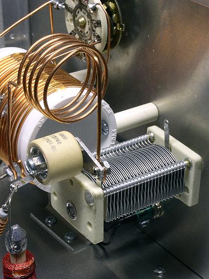
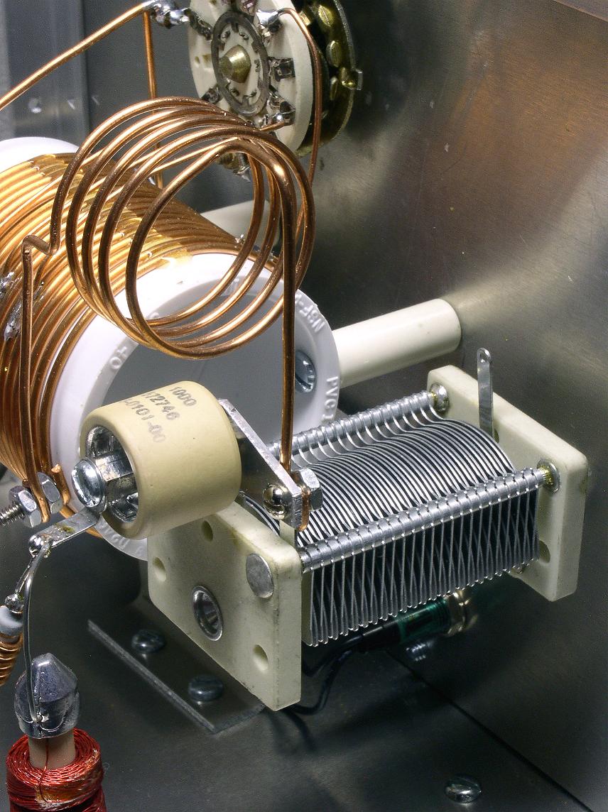
| Plate Tuning Capacitor: The plate tuning capacitor is a 300pf unit purchased from RF parts. The copper coil in the top of the photo is the 10m tank coil. The Centralab "doorknob" plate coupling capacitor is visible on the left. This is a 1000pf 5kv unit designed for transmitter service. Do not try to use "television type" doorknob capacitors in this application. Such capacitors were designed for service in TV high voltage supplies and cannot handle the RF current encountered in transmitter service. |
 Click on the image for a larger view. Click here for a super detailed view. |
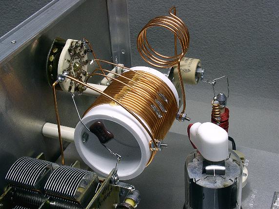
| Plate and
10m Tank Coil: The plate tank coil (large coil in the photo) and 10m Coil (small coil in the photo) are mounted on the back of the front panel. The 10m Coil is not difficult to make, but the plate tank coil is more of a challenge. For more information and construction details on these two coils, click on the links below: Click here for construction details for the 10m Coil Click here for construction details on the plate tank coil Important note: the 10m coil is part of the inductance on all of the bands, so you must include the 10m coil even though you don't plan to operate on 10m.. |
 Click on the image for a larger view. Click here for a super detailed view. |
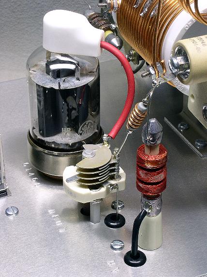
| Neutralizing Capacitor, Parasitic Suppressor, and Plate RF
Choke: The neutralizing capacitor (in the middle of the photo) is at full plate potential and it must have an insulated shaft and it must be insulated from the chassis. The capacitor must be able to handle at least twice the plate voltage on the tube. The capacitor is mounted on white nylon standoff insulators, and the connection to the grid circuit is made through an insulating grommet in the chassis. The parasitic suppressor consists of 5 turns of #16 wire wound on a 100 ohm, 1 watt resistor. In the photo it is connected between the plate coupling capacitor at the upper right and the neutralizing capacitor. The red plate RF choke is a 1mh, 300ma unit (type R300U) purchased from RF Parts. The high voltage connection to the choke is made through an insulating grommet in the chassis. |
 Click on the image for a larger view. Click here for a super detailed view. |
 Click here for pictures and information on the matching 6CL6
one-tube transmitter
Click here for pictures and information on the matching 6CL6
one-tube transmitter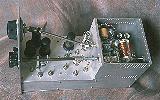 Click here for pictures and information on the Wingfoot
VFO 2E26 Exciter
Click here for pictures and information on the Wingfoot
VFO 2E26 Exciter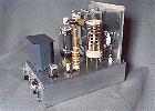 Click here for pictures and information on the Wingfoot
813 Amplifier
Click here for pictures and information on the Wingfoot
813 Amplifier Back to Dr.
Greg Latta's Electrical Engineering and Amateur Radio Pages
Back to Dr.
Greg Latta's Electrical Engineering and Amateur Radio Pages
 If you have any questions or
comments, you can send E-Mail to Dr. Greg Latta at
glatta@frostburg.edu
If you have any questions or
comments, you can send E-Mail to Dr. Greg Latta at
glatta@frostburg.edu
This page is under constant revision. Please check back often.