 Click on the image for a larger view. |
 Click on the image for a larger view. |
| Click on the image for a larger view. |
Click on the image for a larger view. |
| 6x2 Receiver - Main Page and Exterior Photos | Schematic Diagram and Circuit Descriptions |
| Interior Photos | Alignment |
| How To Operate The 6x2 Receiver | Parts and Construction |
| Greger Warna's Receiver | Mechanical Construction |
Comments:
Greg Warna, OH6CN of Finland, took on the challenge of building his own version
of my 6x2 receiver. As you can see from the pictures on this page Greger did a
beautiful job! It took him a good while to gather and/or make the parts for his
receiver but the wait was worth it. His receiver works great and he should be
very proud of what he has accomplished.
The pictures on this page not only show the finished receiver from the outside
but also the inside construction and pictures taken while Greger was in the
process of building the receiver. Some of the pictures show Greger testing his
circuits while he was building them. This is not only educational but a
necessary part of building such a complicated project. The circuits must be
tested before the final build to make sure they work as intended.
Many thanks to Greger for taking the pictures and sending them to me so I can
put them on the web for the benefit of all.
| Exterior Photos |
| Interior Photo |
| Photos While Testing and Under Construction |
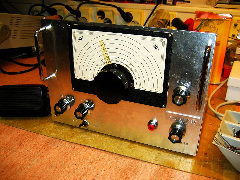
| Front Panel View: This is a picture of the front panel of Greger's finished receiver. He was able to find a beautiful, brand new, National Velvet vernier dial. This is very similar to the one I used in my receiver, but is not illuminated. Greger also added handles to the front of the receiver which permit easier handling of the receiver when moving or working on it. |
Click on the image for a larger view. |
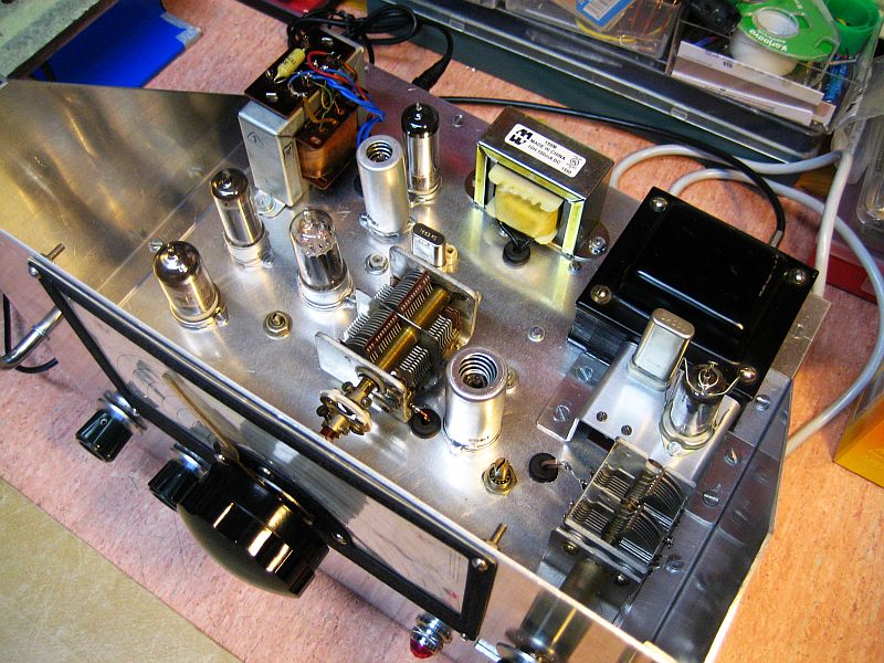
| Top View of the Finished Chassis: Greger's layout is nearly the same as mine. Using the same layout in a receiver is a good idea because changing the layout can sometimes introduce unwanted interactions between some of the circuits. The major difference in Greger's receiver is that he used solid state rectifiers in the power supply, a 7-pin voltage regulator tube rather than an octal tube, and he mounted the power supply filter choke on the top of the chassis, rather than underneath. Greger also has the crystal filter farther away from the mixer, on the upper left of the main tuning capacitor, rather than to the upper right of it |
Click on the image for a larger view. |
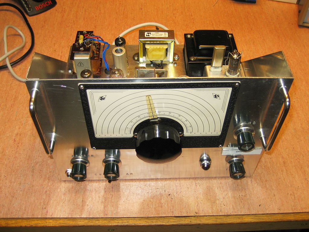
| Front Panel View with Side Panels: One nice touch Greger added to his receiver was a pair of metal side panels to brace the front panel. These stiffen the receiver and permit the addition of handles to the front panel which can be used to carry the receiver. |
 Click on the image for a larger view. |
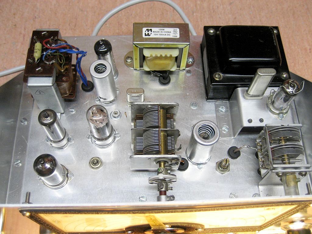
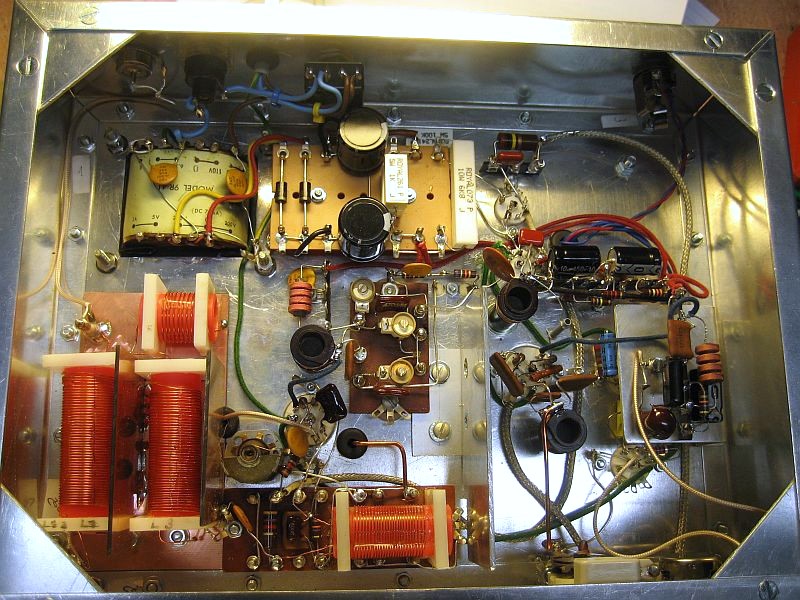
| Top View: This top view of the chassis clearly shows the placement of all of the components. The audio output transformer, filter choke, and power transformer line the tope of the chassis. The main tuning capacitor is at bottom center, and the band select capacitor is at bottom right. The crystal calibrator is elevated on a small sub-chassis between the power transformer and band select capacitor at right. As in my receiver, only the front section of the main tuning capacitor is used. The other unused sections are grounded. |
 Click on the image for a larger view. |
| Under Chassis View: Greger did a fine job of under chassis construction. For many of the circuits he used phenolic work boards to hold the parts, similar to the way parts are mounted in Drake twins such as the R4A and T4X. Coils were mounted by fitting them with square plastic collars that were then mounted to the phenolic boards. The result is sturdy construction that cuts down on microphonics and results in a stable receiver. |
 Click on the image for a larger view. |
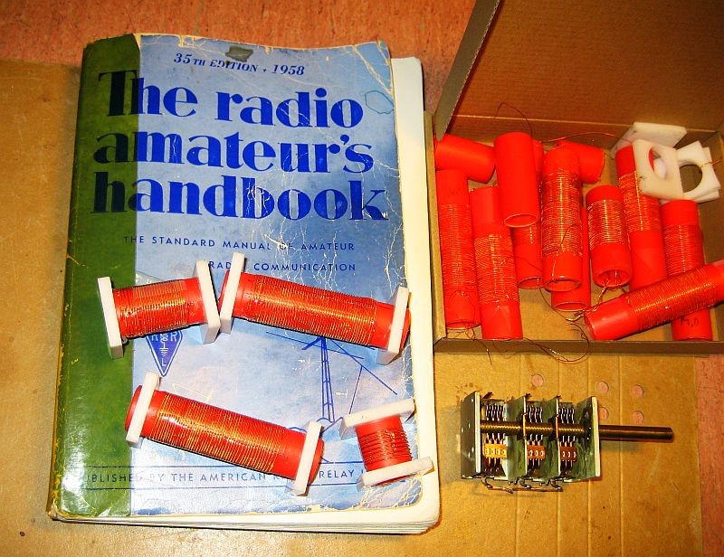
| Winding Coils: Greger spent a lot of time working on the coils for the receiver. Is this photo you can see some of his practice coils along with a 1958 ARRL Handbook and a spare tuning capacitor. Once you get into it, winding coils can be fun! |
 Click on the image for a larger view. |
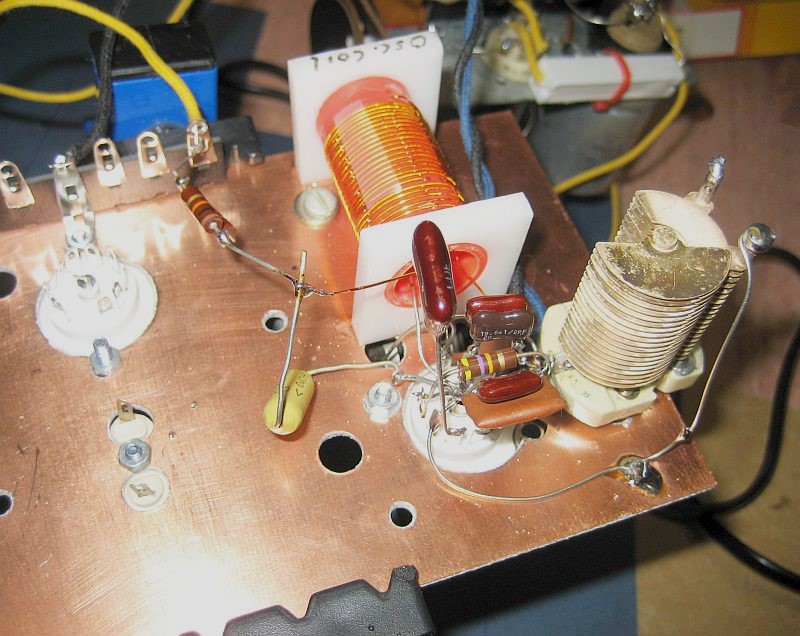
| Testing the Local Oscillator: In this picture, Greger has wired the local oscillator and is testing it. In a project such as this, all circuits should be tested as they are completed to make sure they are working as intended. There are always unexpected problems and this is the only way to catch them. |
 Click on the image for a larger view. |
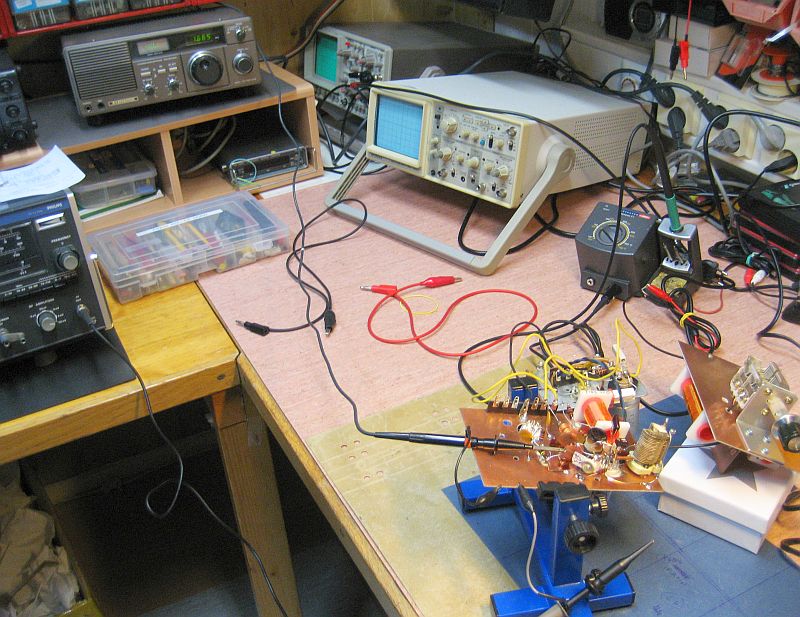
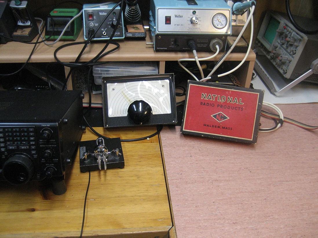
| Testing the Local Oscillator and Front End: After the local oscillator was working, Greger hooked up the front end coils to see if the entire mixer was working. This was done by connecting the output of the mixer to a receiver tuned to the IF, which can be see at top left in the photo. The front end is connected to an antenna, and if signals can be heard in the IF receiver, the mixer is working OK. Again, test all circuits as you go along to avoid disappointment! |
 Click on the image for a larger view. |
| Working on the Chassis: In this picture, Greger is working on the chassis. The power transformer has been mounted and the vernier drive is being held in place to see how it will look when the receiver is finished. |
 Click on the image for a larger view. |
| National Dial: This is a picture of the National Velvet Vernier dial after it was received in the mail. |
 Click on the image for a larger view. |
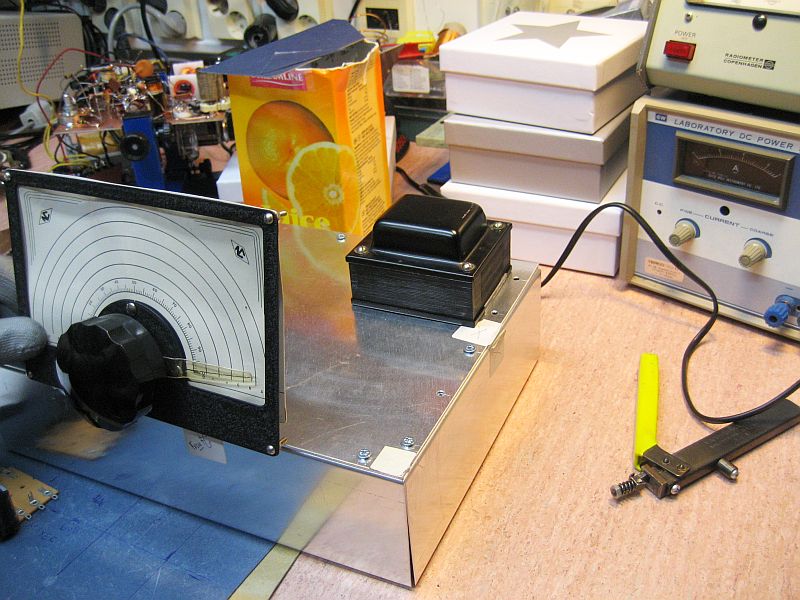
| BFO Testing: After wiring the BFO circuit, Greger hooked it up to an oscilloscope and also to a receiver tuned to the IF frequency to verify that it was working. Greger used an IF of 1665 kHz rather than 1700 kHz because this was the frequency of the coils that he had. |
%2025.12-2016%20004.jpg) Click on the image for a larger view. |
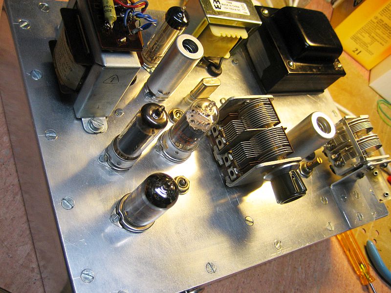
| Almost Done: This is a picture of the top of Greger's receiver before the front and side panels have been mounted. The vernier for the main tuning capacitor is also absent. |
 Click on the image for a larger view. |
 Back to Dr. Greg Latta's
Electrical Engineering and Amateur Radio Pages
Back to Dr. Greg Latta's
Electrical Engineering and Amateur Radio Pages
 If you have any questions or
comments, you can send E-Mail to Dr. Greg Latta at
glatta@frostburg.edu
If you have any questions or
comments, you can send E-Mail to Dr. Greg Latta at
glatta@frostburg.edu