
Click on the image for a larger view. Click here for a super detailed view. |
 Click on the image for a larger view. Click here for a super detailed view. |
|
Click on the image for a larger view. Click here for a super detailed view. |
Click on the image for a larger view. Click here for a super detailed view. |
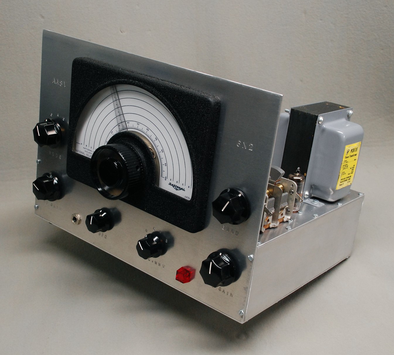
| 6x2 Receiver - Main Page and Exterior Photos | Schematic Diagram and Circuit Descriptions |
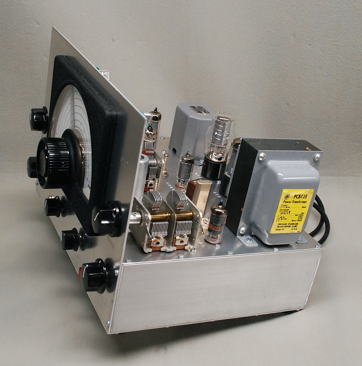
| Interior Photos | Alignment |
| How To Operate The 6x2 Receiver | Parts and Construction |
| Greger Warna's Receiver | Mechanical Construction |
Introduction:
The 6x2 receiver is capable of very good performance given its simplicity.
However, to achieve maximum performance it is necessary to understand the
receiver's limitations. These include manual IF gain control and selectivity
that is a compromise between CW operation and SSB operation.
Initial Adjustment For CW Reception:
Connect a speaker and antenna to the receiver. Though the receiver is so
sensitive that a wire thrown across the floor will work as an antenna, it will
work much better connected to a proper antenna. Turn on the receiver and set
the mode switch to CW.
Set the audio gain about 1/3 the way up and advance the IF gain control until
noise is heard in the receiver. Adjust the BFO control slightly to the
right side (clockwise, higher frequency side) of BFO zero beat. (Zero
beat on the BFO control is where the pitch of the noise is the lowest.) Tune
the band select control through its range and you should find four peaks. Two
will occur with the plates more meshed, and two will occur with the plates less
meshed. The two peaks with the plates more meshed are the 80m band. The other
two are the 40m band. From either pair of peaks, always use the peak with the
plates less meshed. This will provide for the best rejection of the
unwanted band.
Use the main tuning control to tune through the band, and you should hear
signals. As you tune through the band, you will have to occasionally repeak the
band control. Remember that the lowest frequency on the 80m band is 3500kHz,
but the lowest frequency on the 40m band is 6900kHz. (If you turn on the
crystal calibrator, the second peak on the 40m band corresponds to
7000kHz).
On the 80m band, you should get a much stronger response when the main tuning
control is on the low side of zero beat. On the 40m band, the strongest
response will be on the high side of zero beat. Once you have found a
signal, adjust the main tuning control and BFO control for the strongest
response on the pitch at which you like to listen to CW.
Receiving Single Sideband (SSB):
To receive SSB signals, the BFO must be set properly. To receive LSB signals on
the 40m band, the BFO should be set as for CW, with the BFO control slightly to
the right (clockwise) of BFO zero beat. Tune in the signal for the
clearest reception. You will have to experiment with the BFO to find the best
setting.
For LSB signals on 80m, the BFO must be set to the left
(counterclockwise) of BFO zero beat. Tune in the signal for the clearest
reception. You will have to experiment with the BFO to find the best setting.
Fidelity on 80m is not as good as on 40m because of a naturally occurring notch
in the crystal filter. Remember, the 6x2 is optimized for CW reception, not for
SSB.
Audio Gain Control:
The audio gain or "Volume" control sets the gain of the audio
amplifier. In typical operation, set the audio gain control at about the 9 or
10 o'clock position, or 1/4 to 1/3 the way up. Then use the IF gain control to
set the final volume. These are only guidelines, but I typically never have to
run the audio gain control control past the 10 o'clock position. See the
information below on using the IF gain control.
Manual IF Gain Control:
One of the biggest differences between modern receivers and the 6x2 is that the
6x2 does not have automatic gain control (AGC) in the IF amplifier. Modern
receivers automatically turn up the gain to a maximum, and cut the gain back as
needed to equalize the signal levels. As the level of a signal rises, the IF
gain is decreased, and as the signal becomes weaker the IF gain is increased.
The result is a relatively constant signal level in the speaker. AGC is great,
but implementing AGC in a homebrew receiver greatly complicates the design and
construction. It turns out that during a QSO signal levels often vary slowly
over time, so manual control is fine. The difficulty is in finding the initial
setting of the control when calling or answering a CQ.
Listening For Stations Calling CQ:
When scanning the band on CW for a station calling CQ, set the control high
enough to hear weaker signals, but not so high as to overload on the stronger
signals. Set the IF gain about half way up, and tune slowly and listen
carefully so you don't miss any weaker signals. If you hear a weak signal of
interest, advance the IF gain control until you can hear the station. (Don't
turn up the audio gain, turn up the IF gain.) If you decide to move on,
turn the IF gain back down so you don't overload on the stronger signals. Don't
be afraid to run the control at its extremes. I typically operate with the IF
gain control all the way down, but sometimes I must advance it nearly all the
way up to copy a QRP station. It just depends on band conditions and the
station.
Calling CQ And Listening For A Reply:
When calling CQ on CW, the situation is somewhat easier, since you will
presumably be calling on a clear frequency. One technique is to set the IF gain
about 1/2 way up when listening for a reply. However, be sure to listen very
carefully for a weak station replying. Turn the control up quickly if the
station is too weak. (Don't turn up the audio gain, turn up the IF
gain.) Another technique is to have the IF gain set near the maximum so you
don't miss a reply from a weaker station. However, be ready to quickly turn
it down if a stronger station replies. I prefer to use the 1st method,
since I usually run the control near its minimum setting.
Optimizing The BFO Setting For CW:
The proper BFO setting for CW is critical for the best performance of the 6x2
receiver. Contrary to what some may think, setting the BFO on the proper side
of BFO zero beat for CW reception does make a difference! As explained
under the section on initial adjustment the
BFO should be set on the higher frequency side of BFO zero beat (where
the pitch of received noise is the lowest) for all CW reception. The
presence of a deep, naturally occurring notch in the crystal filter will then
help to suppress the CW audio image, providing very good single signal
reception.
One way to find the optimum BFO setting for CW is to do the following:
1. Set the receiver for the 40m band.
2. Set the IF gain to a minimum.
3. Turn on the crystal calibrator and tune through the calibrator signal. You
should notice a much stronger response on the higher frequency side of zero
beat. (Detune the band control to reduce the signal strength if necessary.)
Tune in the signal for the strongest response, even if the audio pitch
is higher or lower than you may be used to. The goal is to find the setting of
the main tuning control that produces the strongest response, regardless of the
audio pitch. This places the signal in the middle of the crystal filter
passband.
4. Finally, adjust the BFO control for the audio pitch you are most comfortable
with. (Be sure this is on the high side of BFO zero beat).
The BFO setting is now optimized for CW reception.
Once optimized, you will notice that, on the main tuning control, CW
signals on the 40m band are received on the higher frequency side of
zero beat and on the 80m band they are tuned in on the lower frequency
side of zero beat. That they are received on opposite sides of zero beat is a
result of the mixing scheme used in the 6x2 receiver.
AM Operation And WWV Reception:
For AM operation, set the mode switch to AM and turn the IF gain control all
the way up. (The AM detector requires a lot of signal to operate properly).
To receive WWV at 5Mhz, set the mode to AM and the Calibrate/WWV switch to WWV.
Set the main tuning dial to the bottom of its range. Adjust the Band control to
a point between the 80m and 40m positions where the noise peaks and you should
then be able to tune in WWV. (Note that tuning is much broader on the WWV band
than on the 80m and 40m bands.)
When receiving WWV with the Calibrate/WWV switch set in the WWV position, a
pair of peaks will be found on the band control between the 80m and 40m
positions. Use the peak with the plates less meshed for the best image
rejection.
Fidelity will not be good because of the narrow crystal filter, but it will be
good enough to set your clock. (Remember, WWV on 5Mhz comes in only long after
dark, so you must wait till late in the evening before you can hear it.)
Band Control:
The band control determines which band the receiver will receive. Tuning the
band select control through its range will show four peaks. Two will occur with
the plates more meshed, and two will occur with the plates less meshed. The two
peaks with the plates more meshed are the 80m band. The other two are the 40m
band. From either pair of peaks, always use the peak with the plates less
meshed. This will provide for the best rejection of the unwanted band.
It is normal for the setting of the Band Control to slightly affect the setting
of the main tuning control. Simply peak the Band Control first and then tune in
the station with the main tuning control. (This effect is caused by the close
coupling between the mixer and the antenna, and is a downside of the 6x2
design.)
When receiving WWV with the Calibrate/WWV switch set in the WWV position, a
pair of peaks will be found between the 80m and 40m positions. Use the peak
with the plates less meshed for the best image rejection.
When tuning through a band it will be necessary to sometimes repeak the band
control for best sensitivity. In addition, if overload or "pulling" occurs with the
IF gain control at its minimum setting, you can detune the band control to
lessen the signal strength and prevent overload.
Calibrate/WWV Switch:
The Calibrate/WWV switch has four positions as follows:
1. Off
2. Calibrate - Crystal calibrator is turned on.
3. WWV - WWV band is selected. Crystal calibrator is turned off.
4. Both - WWV band is selected and crystal calibrator is turned on. (This
position is normally used only when aligning the crystal calibrator.)
The crystal calibrator is used for calibrating the main tuning control. With
the receiver set to receive CW and the calibrator is on, strong marker signals
will be heard on the following frequencies:
80m: 3500kHz (bottom end of main tuning scale), 3600KHz, 3700kHz, and 3800kHz.
40m: 6900kHz (bottom end of main tuning scale), 7000kHz, 7100kHz, and 7200kHz.
Note that the 40m band begins at the second marker.
Improving Receiver Performance With An Audio
Filter:
Though the 6x2 receiver can stand on its own, an external audio filter will
greatly improve the performance. The extra selectivity will make up for the
relatively wide intrinsic selectivity of the 6x2, which is a compromise for
both CW and SSB reception.
Over the years I have found that an external audio filter can improve the
performance of even the best modern receivers. Several manufacturers such as
Timewave and MFJ make these, and there are designs for such filters in many of
the ARRL handbooks. I have personally used a Heathkit HD-1814 audio filter with
all of my receivers for many, many years. I would be lost without it.
Receiver Overload And Strong Signal
Pulling:
On very strong CW signals you may notice that the pitch of the signal changes
very slightly at a slow, irregular rate. I have noticed this often when
receiving W1AW code practice on 7047.5kHz. This is caused by overload of the
receiver front end. These signals get coupled to the local oscillator through
the grid-cathode capacitance of the 6U8A mixer tube and "pull" or
slightly change the local oscillator frequency. The amount of the pulling
changes as the strength of the received signal varies with propagation.
The solution is to detune the band control until the pulling stops. I
have also found that replacing the 6U8A mixer tube with a 6GH8A tube improves
the overall performance of the receiver and makes the receiver less prone to
pulling. However, even with the 6GH8A, I have noticed pulling on extremely
strong signals. This is one of the downsides of the 6x2 design, where the mixer
is closely coupled to the antenna. It is something you must learn to live with.
Transmit Mute:
The 6x2 receiver must be muted during transmit periods. Because the 6x2
lacks an AGC circuit to reduce the IF gain on strong signals and because of the
powerful audio amplifier, failure to mute the receiver during transmission can
cause speaker burnout at worst and major discomfort to the operator at the
best. Do not try disconnecting the speaker as a method of muting the
receiver!. This would leave the audio amplifier unloaded and could cause
damage to the output transformer. Instead, the 6x2 features a
transmit mute
circuit in the IF amplifier to mute the receiver during transmission. The
mute contacts must be connected together (or the mute switch contacts must be
closed) for normal receive operation.
To manually mute the receiver, simply open the mute switch. To use a
remote/automatic mute circuit, open the mute switch and connect a set of remote
mute contacts to the mute jack on the receiver. When the remote mute contacts
are closed, the receiver will operate normally. When the mute contacts are
opened, the IF gain is greatly reduced, and the receiver is muted.
 Back to Dr. Greg Latta's
Electrical Engineering and Amateur Radio Pages
Back to Dr. Greg Latta's
Electrical Engineering and Amateur Radio Pages
 If you have any questions or
comments, you can send E-Mail to Dr. Greg Latta at
glatta@frostburg.edu
If you have any questions or
comments, you can send E-Mail to Dr. Greg Latta at
glatta@frostburg.edu