The AA8V 6x2 Superheterodyne Receiver
by Greg Latta, AA8V
Mechanical Construction
Introduction:
Building a receiver such as the 6x2 receiver is a formidable project and should
not be entered into lightly. Building a tube superheterodyne receiver or SSB
transmitter is perhaps the most difficult project a builder can ever undertake.
As manufacturers in the 1940s and 1950s quickly found, robust construction is
necessary, particularly when it comes to the local oscillator and BFO
components. These components must be mounted very securely to avoid drift and
microphonics. Fortunately for us, these requirements are somewhat easier in the
6x2 receiver because, except when receiving WWV, the local oscillator always
operates on the same frequency. The number of sensitive components in the local
oscillator is much less than the number required in a general coverage or five
band receiver, and this makes construction much easier. For example, there is
only one local oscillator coil rather than five or six, and this greatly
simplifies construction.
Tube gear utilizes components that are larger and heavier than solid state
gear, and this means the chassis must be stronger to handle the extra weight.
Heavy components, such as transformers and chokes, must be mounted as close to
the sides and other support structures as possible. This minimizes flexing of
the chassis, which can lead to frequency instability and microphonics. The main
tuning capacitor must be mounted in a very stiff area where any movement is
impossible, and the alignment between the vernier dial and the main tuning
capacitor must be adjustable so that any biniding can be eliminated. The
movement of the main tuning capacitor and vernier dial must be absolutely
smooth if good tuning characteristics are to be achieved.
Approximate Dimensions
| Approximate Dimensions:
The main chassis of the 6x2 receiver is a box constructed of aluminum sheet and
bar stock. A thick front panel made of aluminum sheet is then securely fastened
to the box.
The main chassis dimensions are approximately 12" wide, 9" deep, and
3" high. The sides are made of 3" wide x 9"long x 1/4"
thick aluminum bar stock, and the top, bottom, front, and back panels are made
out of 1/16" thick sheet aluminum. The dimensions of the top, bottom,
front, and back panels are adjusted/sanded to give a clean tight fit when the
chassis is assembled.
The front panel is made of 3/32" thick sheet aluminum, 12" wide and 8
1/2" high. The front panel is held onto the main chassis with four 4-40
screws and the shafts of the AF GAIN, BFO, CALIBRATE, and IF GAIN controls.
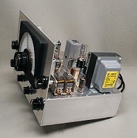
If you zoom in on this super detailed side view
you will get a good idea of how the chassis and front panel are structured.
|
Click on the image for a larger view.
Click here for a super detailed
view. |
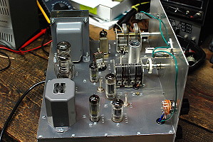
Main Chassis Construction
| Main Chassis Construction:
The main chassis of the 6x2 receiver is a box constructed of aluminum sheet and
bar stock. Though a commercially made chassis made of bent/folded aluminum
could certainly be used, I prefer this type of construction because I am
familiar with it and it results in a firmer, more rigid chassis. This is the
same construction that I used in my 6146
Amplifier and my Wingfoot
813 Amplifier. Rigid construction, so neccessary for stability, is even
more important in a receiver than it is in an amplifier.
The main chassis dimensions are approximately 12" wide, 9" deep, and
3" high. The two side panels are made of 3" wide x 9" long x
1/4" thick aluminum bar stock. The top, bottom, front, and back panels are
made out of 1/16" thick sheet aluminum. The dimensions of the top, bottom,
front, and back panels are adjusted/sanded to give a clean tight fit when the
chassis is assembled.
The side panels are drilled and tapped on all four sides to accept 4/40 screws.
The other panels are then fastened to the side panels with 4/40 pan head
screws.
Note that the front panel does not form the front side of the chassis. There is
a separate 1/16" panel between the receiver front panel and the
front of the side panels. This construction allowed me to mount the front panel
controls on the 1/16" panel while testing and developing the receiver, and
then add the final front panel later. It also provides strength and support
to the front side of the top panel, which is very important. Do not omit
it! (This extra panel is more easily seen in the photo below.)
If you zoom in on this super detailed rear view
you will get a good idea of how the main chassis and front panel are put
together.
|

Click on the image for a larger view.
Click here for a super detailed
view. |
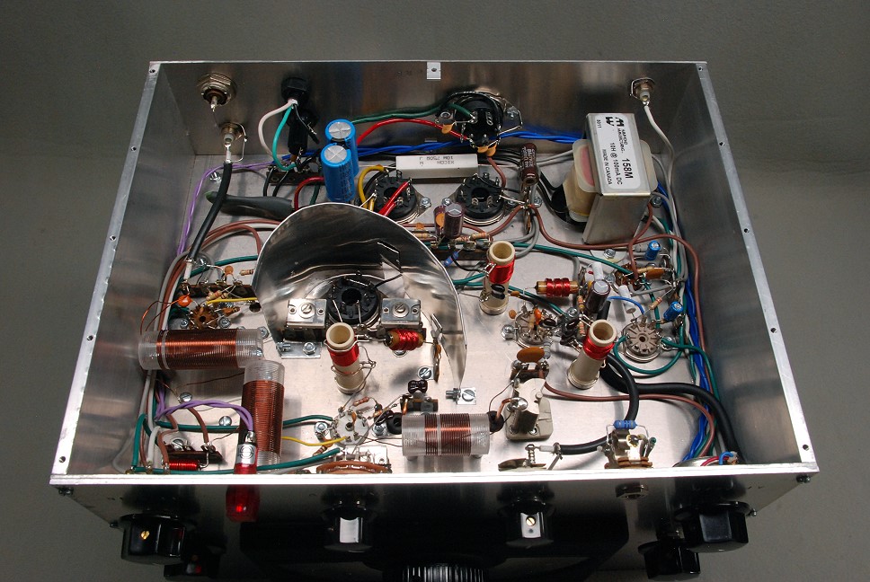
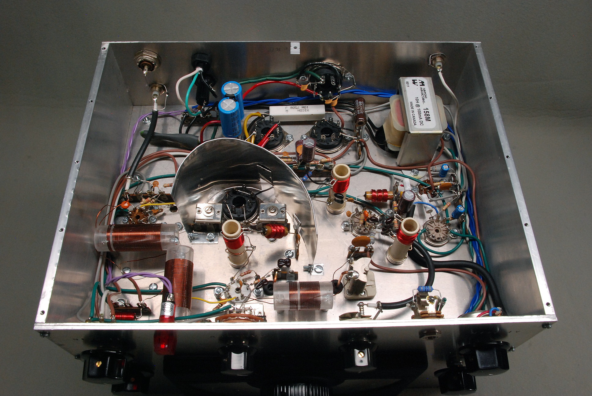
| Main Chassis Bottom View:
In this bottom view of the main chassis you can clearly see the holes in the
1/4" x 3" side panels that have been drilled and tapped to accept the
screws that hold on the bottom panel. If you carefully look at the back panel
at the rear of the photo you will also two see small "L" brackets
that are attached to the middle of the back panel. (One is behind the white
ceramic resistor at the rear of the photo). These are drillled and tapped to
accept 4-40 screws. These connect the back panel to the top and side panels to
provide additional support for the back panel and to eliminate the possibility
of vibration.
If you look carefully at the front of the photo you will see that there is a
1/16" panel between the actual front panel of the receiver (which is
3/32" thick) and the front of the side panels. The two panels are held to
the side panels with four 4-40 pan head screws. The front panel controls pass
through both panels. This construction allowed me to mount the front panel
controls on the 1/16" panel while testing and developing the receiver, and
then add the final front panel later. It also provides strength and support
to the front side of the top panel, which is very important. Do not omit
it!
|
Click on the image for a larger view.
Click here for a super detailed
view. |
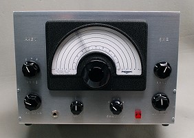
Front Panel Construction
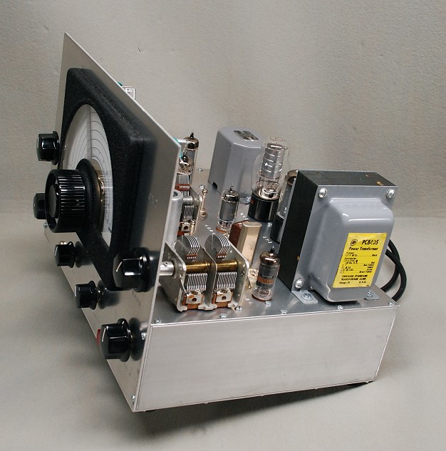
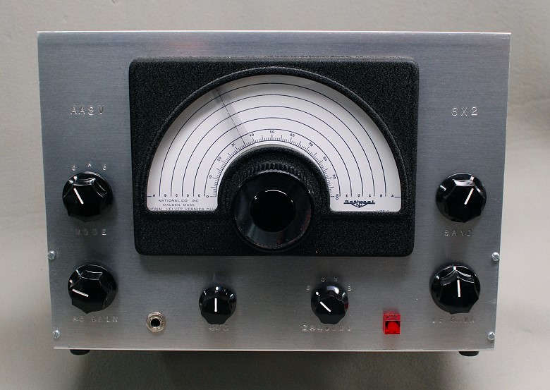
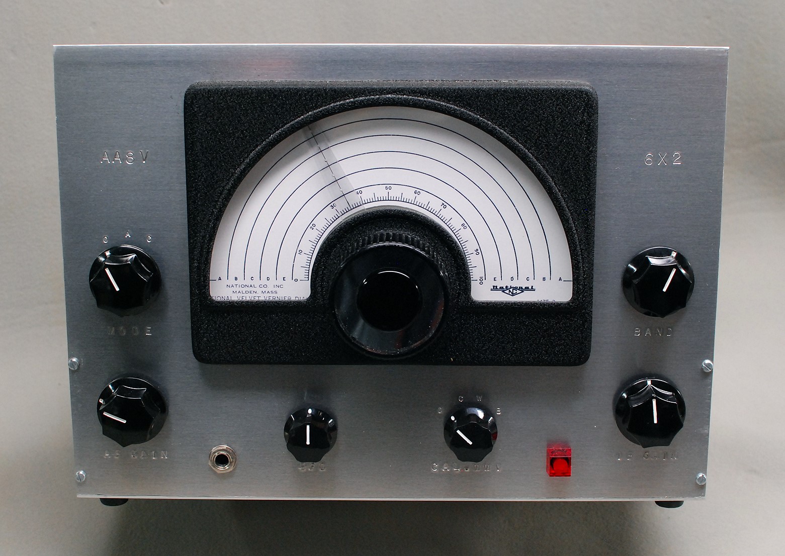
| Front Panel Construction:
The front panel is made of a single piece of brushed aluminum 12" wide, 8
1/2" high, and 3/32" thick. Do not use thinner aluminum. Thick
aluminum is necassary to prevent the front panel from flexing during operation.
Thinner aluminum will flex, for example, when the receiver is tuned,
introducing slop and backlash.
Control functions are stamped into the front panel using metal letter/numbering
stamps available from sources such as Harbor
Freight Tools and MSC Direct. You
must be very careful when using these stamps, since you can't erase a mistake!
Practice with them first before making the final impressions on the front
panel. You can, of course, also use stencils or a label maker.
The National ICN illuminated dial is mounted to the front panel and connected
to the main tuning capacitor through a flexible coupling whcih smooths out the
tuning. The mounting holes for the ICN dial and the through hole for the tuning
shaft must be slightly larger than normal so the dial can me moved around for a
perfect fit with the main tuning capacitor shaft. Alignment must be done
after the front panel has been mounted to the base of the receiver.
There must be absolutely no binding with the main tuning capacitor shaft. Once
in the proper position, the ICN dial can be tightened into place.
|
Click on the image for a larger view.
Click here for a super detailed
view. |
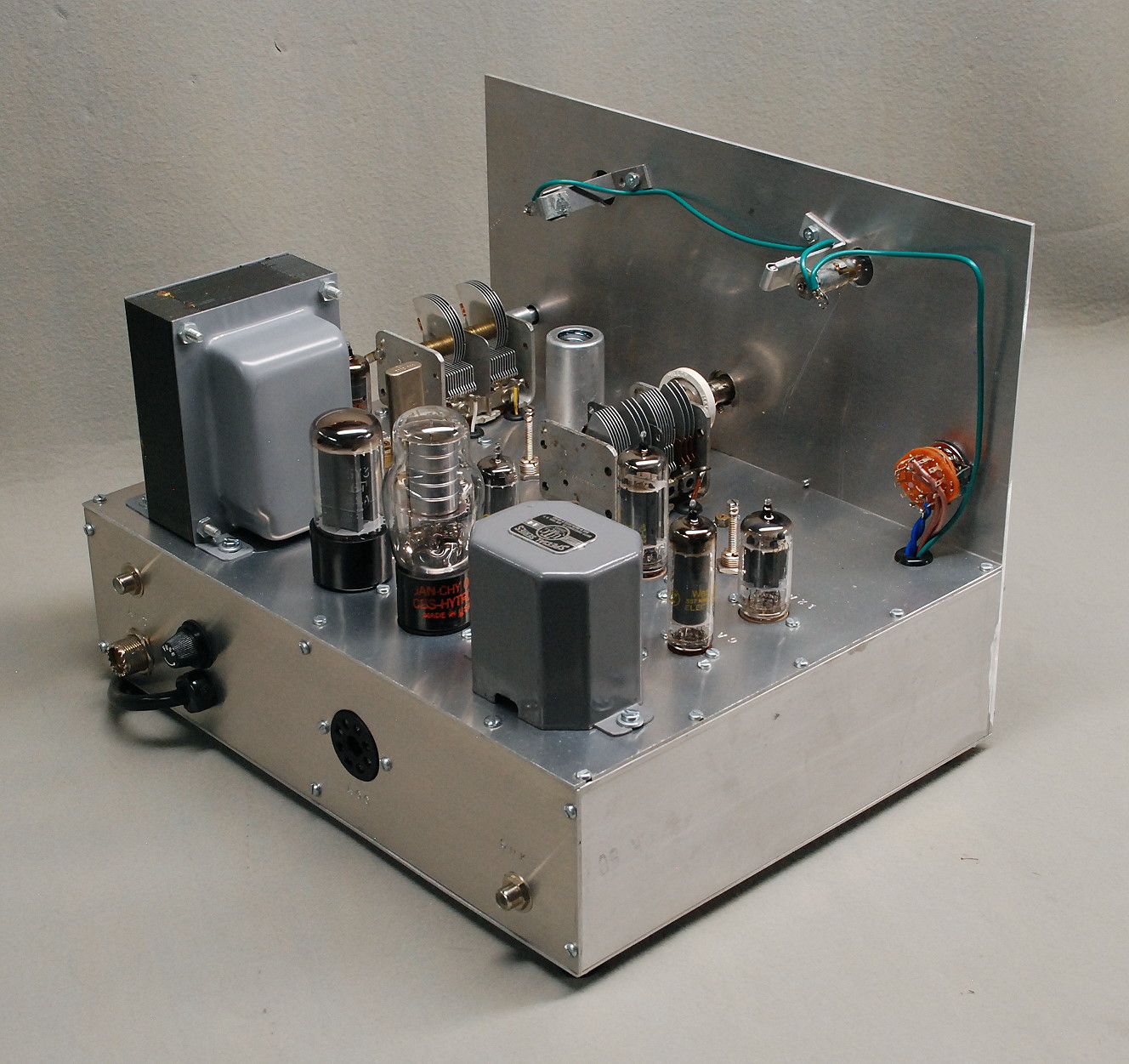
| Front Panel Rear View:
In this picture the back of the front panel can be clearly seen. The shaft of
the band capacitor (the dual section capacitor at left in the photo) passes
through a generous hole in the front panel to prevent binding.
The shaft from the National ICN vernier dial extends through a generous opening
near the center of the front panel. The ICN dial is mounted so that it can be
moved around to obtain perfect alignment with the main tuning capacitor. After
perfect alignment is obtained, it is then secured to the front panel.
I was lucky to have a brand new ICN dial with all of the original
hardware. The #47 pilot lamps that illuminate the dial mount on hardware
provided with the dial. They pass through holes in the front panel and extend
into the housing of the ICN dial. If your dial lacks the original hardware, you
will have to improvise based on the photo.
The MODE switch is mounted on the front panel at right in the photo. Wires to
the MODE switch and pilot lamps pass through a grommeted hole in the top of the
chassis.
|
Click on the image for a larger view.
Click here for a super detailed
view. |
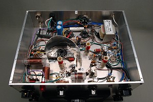
Top Panel Construction:
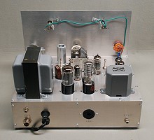
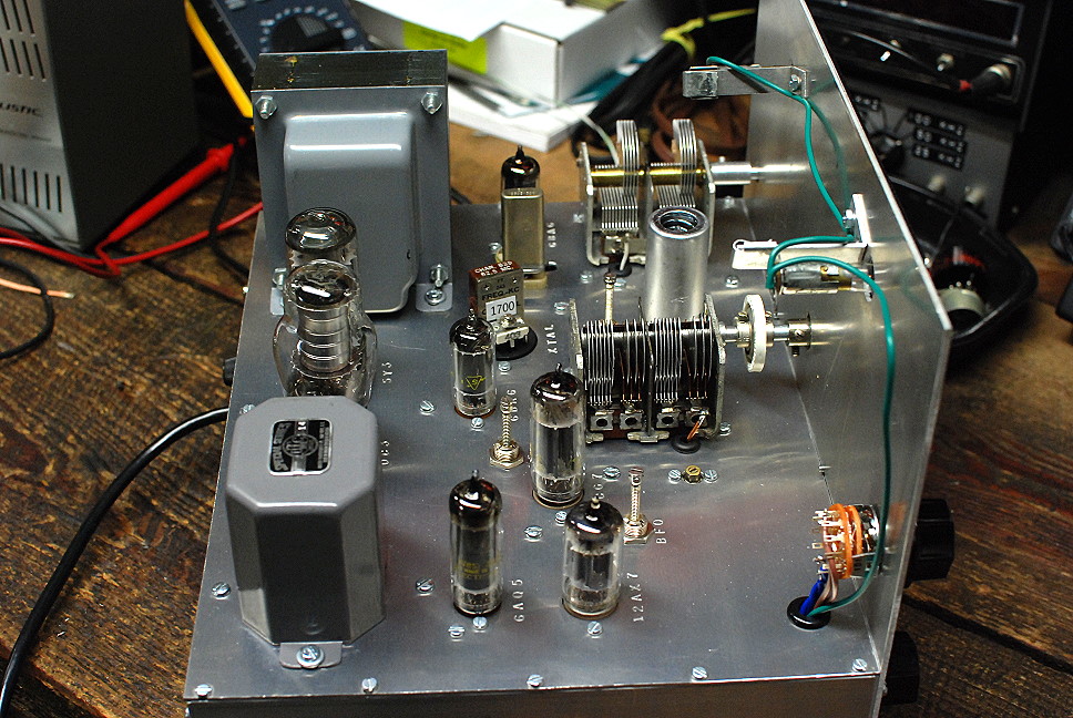
| Top Panel Construction:
The top panel holds most of the receiver components. The top is supported on
all four sides by panels underneath all four edges. This is very important in
preventing any flexure of the top panel which can lead to microphonics. Though
the receiver does have slight microphonics, they are at the same level as
commercial receivers such as my Hallicarafters SX-96.
Like the controls on the front panel, the components and tube sockets on the
top panel are labeled with their functions by using metal letter/numbering
stamps available from sources such as Harbor
Freight Tools and MSC Direct. You
must be very careful when using these stamps, since you can't erase a mistake!
Practice with them first before making the final impressions on the panel. You
can, of course, also use stencils or a label maker, but heat from the receiver
may discolor some of these.
The most critical tube, the 6U8A mixer, is mounted directly behind the front
panel as close as possible to the main tuning capacitor, which is near the
center of the photo. A tube shield is used on the mixer tube to shield it from
any external fields. Only the front 35pf section of the main tuing capacitor is
used. Though not visible in the photo, the stators of the other three unused
sections are shorted to ground to prevent their interacting in any way with the
active section.
The power transformer and output transformer are mounted near the edges of the
top panel to provide firm support. Holes for these were made with an
Adel Nibbling Tool, a tool every serious
builder should own. Holes for the tube sockets were punched using Greenlee
chassis punches. These are expensive, but worth the cost if you make more than
one piece of gear. Lacking chassis punches, the
Adel Nibbling Tool can be used to make
the holes.
Any wires passing through the top panel, such as those from the band capacitor,
main tuning capacitor, and mode switch, should be passed through grommeted
holes.
The crystal Y1 and crystal filter phasing capacitor C3a are mounted in an octal
socket which allows some experimentation with these. These must be as close to
the output of the mixer as possible. The crystal Y3 for the crystal calibrator
is mounted in a cermanic socket directly behind the the band capacitor. Tubes
that produce a lot of heat, such as the 5Y3 rectifier and 6AQ5 audio power
amplifier, are mounted as far as possible from the local oscillator and BFO to
prevent their heat from producing drift.
|
Click on the image for a larger view. |
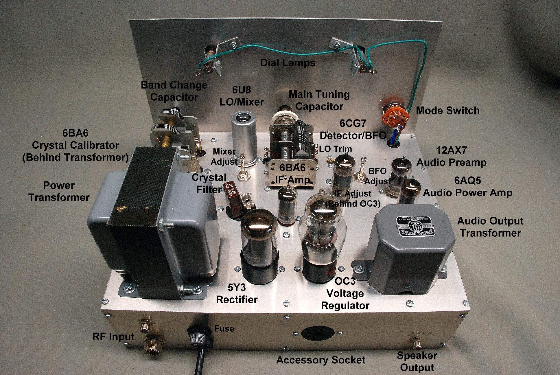
Notated Top And Rear View:
This is a notated view of the top and rear panels of the receiver. All of the
parts mounted on the top and back of the receiver and their functions are
marked. All receiver adjustments that can be made from the top of the receiver
are also marked
The 6BA6 crystal calibrator is not visible because it is behind the power
transformer. Also, the IF adjustment is hard to see. The tip of the IF
adjustment is just barely visible behind the top of the OC3 voltage regulator
tube.
|

Click on the image for a larger view.
Click here for a super detailed
view. |
Rear Panel Construction:
| Rear Panel Construction:
Like the front panel, rear panel functions are stamped into the back panel
using metal letter/numbering stamps available from sources such as
Harbor Freight Tools and
MSC Direct. You must be very careful
when using these stamps, since you can't erase a mistake! Practice with them
first before making the final impressions on the front panel. You can, of
course, also use stencils or a label maker.
At left in this photo of the receiver back panel you can see two antenna
connectors, an RCA and an SO-239. These are connected in parallel and allow the
receiver to be used with just about any system, without having to resort to an
adaptor. To the right of the antenna connectors is the line fuse and line cord.
An octal socket is mounted on the back panel as an accessory power socket to
run accessories such as a converter. The speaker output is the RCA connector on
the far right.
Note the two pan head screws in the middle of the panel at the top and bottom.
These are attached to small "L" brackets that connect the back panel
to the top and bottom panels for additional stability.
Not shown in this picture are an RCA mute jack and mute toggle switch that give
the receiver manual/automatic mute capability. These were
added later, after the
receiver was finished. They were mounted between the line cord/fuse and
accessory socket.
|
Click on the image for a larger view.
Click here for a super detailed
view. |
Mechanical Parts and Tool
Sources
MSC Direct:
MSC Direct is a large industrial supplier. They are happy to work with small
individual buyers, and have monthly sales flyers that usually contain great
deals. They often have special sales where you can get free shipping or 10% to
30% off. I recommend getting on their mailing list to receive their monthly
sales flyers. They not only carry tools, but also raw materials, such as
aluminum and brass. If you wait for one of their special deals, you can get
your aluminum or brass on sale and get it shipped shipped free of charge too.
MSC Direct
OnLineMetals.com:
For any kind of metal or plastic you can't beat OnLineMetals.com. They carry
every conceivable metal and plastic in every form you can imagine.
OnLineMetals.com
Adel Nibbling Tool:
The Adel Nibbling Tool allows you to make
large and small holes of any shape and size above 7/16" diameter in sheet
metal up to about 1/16" thick. You first drill a 7/16" hole through
which you slip the nibbling head. You can then nibble the metal away into any
shape you want. It is great for making transformer holes, meter holes,
rectangular holes, etc. It is an absolute must for anyone who is building tube
gear. I have used one for years and cannot live without it.
 Back to Dr. Greg Latta's
Electrical Engineering and Amateur Radio Pages
Back to Dr. Greg Latta's
Electrical Engineering and Amateur Radio Pages
Questions, Comments, and E-Mail
 If you have any questions or
comments, you can send E-Mail to Dr. Greg Latta at
glatta@frostburg.edu
If you have any questions or
comments, you can send E-Mail to Dr. Greg Latta at
glatta@frostburg.edu
Thanks for stopping by!


