
Click on the image for a larger view. Click here for a super detailed view. |
 Click on the image for a larger view. Click here for a super detailed view. |
|
Click on the image for a larger view. Click here for a super detailed view. |
Click on the image for a larger view. Click here for a super detailed view. |
Introduction:
There are many adjustments that must be made to a superheterodyne receiver to
get optimum performance from the receiver. Most of these are set only once and
then left alone. The adjustment of these is called "aligning the
receiver" or "receiver alignment". Most commercial receiver
manuals contain instructions on receiver alignment. However, aligning a
commercial receiver can be a complicated process and should not be attempted
unless you have the proper test equipment and are thoroughly familiar with the
process. Many alignment procedures are common to all superheterodyne receivers,
but many receivers have there own idiosyncracies and alignment requirements.
I am providing the following details on aligning the 6x2 because it is one of
the least complicated communications grade receivers one is likely to
encounter. That means it is much easier to align than a commercial receiver,
and you should be able to follow the procedure and get a good understanding of
what is being done and why it is being done.
For the 6x2 receiver, the following must be aligned:
1. Mixer plate coil and IF amplifier plate coil (IF Alignment)
2. Initial BFO Alignment
3. Local Oscillator Bandset Capacitor
4. Front End Trimmer Capacitor
5. Final BFO Alignment
6. Crystal Filter Voltage Divider Capacitors
7. Crystal Filter Phasing Capacitor
8. WWV Trimmer Capacitor
9. Crystal Calibrator Trimmer Capacitor
Equipment Needed:
Touching up the alignment of an operating receiver can sometimes be achieved by
using antenna noise or the internal crystal calibrator as a signal source.
However, alignment of a new receiver or one severely out of alignment is best
done using a VOM/Multimeter, an amplitude modulated signal generator, and a
frequency counter or calibrated short wave receiver. For the 6x2 receiver, a
capacitance meter is also helpful.
| VOM/Multimeter: A VOM/Multimeter is the most basic measurement tool. Every electronics work bench needs at least one. For alignment purposes, a modern digital VOM can be used, but it should have an analog scale on it, since the meter is going to be used to maximize a signal, rather than read its actual value. Far better is a true analog VOM. Such meters are much better for alignment purposes because the movement of the meter is not digitized, and the tiniest changes in the signal can be detected. I used the meter shown at right for aligning the 6x2 receiver. |
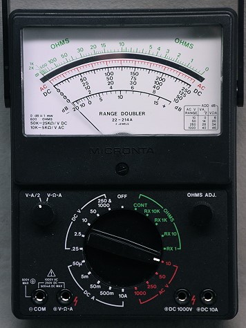 True Analog VOM - Much Better For Alignment Than A Digital VOM |
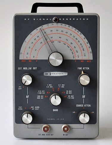 Heathkit IG-102 Signal Generator Every electronics builder or experimenter should own a signal generator. |
Signal Generator: The signal generator must cover the same frequencies as those covered by the receiver, and it must also cover the IF frequency. For the 6x2, this means a signal generator that covers 1700kHz to 7500kHz. Many years ago I built the Heathkit IG-102 signal generator shown at left and have found it invaluable. I use it for everything. Signal generators such as this can often be found at hamfests or on e-bay at very reasonable prices, and every builder or experimenter should own one. |
| Frequency Counter or General Coverage Short
Wave Receiver: A frequency counter is a big help in adjusting the local oscillator and the BFO. It need not be fancy, since the frequency of these oscillators is only a few MHz. If a frequency counter is not available, an accurate general coverage short wave receiver can be used. It must be able to receive 1700kHz and 5200kHz (1.7Mhz and 5.2MHz). At right is an Optoelectronics counter I built many years ago and still use today. |
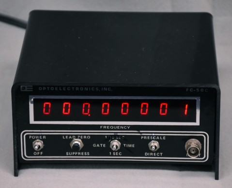 Frequency Counter - Used for BFO And Local Oscillator Alignment |
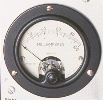
 Capacitance Meter - Another Very Useful Shop Tool |
Capacitance Meter: A capacitance meter is needed to adjust the crystal filter input balancing capacitors to the same value before they are installed in the receiver. If the receiver is already built, the capacitance meter is not needed. |
Alignment Order:
The order of alignment depends somewhat on the receiver. Usually, the IF is
aligned first, followed by the BFO. After the IF and BFO are aligned, the local
oscillator and RF amplifier are aligned. The last things to be aligned are the
crystal filter and crystal calibrator.
Mixer Plate Coil And IF Amplifier Plate Coil (IF
Alignment):
The IF amplifier is
usually the first stage to be aligned in a superheterodyne receiver. If the IF
amplifier is severely out of alignment, virtually no signals will get through
the receiver.
To align the IF amplifier, a signal at the correct frequency must be lightly
coupled to the IF amplifier in a manner such that it will not affect the
alignment of the IF amplifier. In the 6x2 receiver, this is most easily done by
connecting the signal generator output to the grid (pin 2) of the
6U8A mixer tube.
To align the IF amplifier in the 6x2 receiver, do the following:
1. Connect a speaker to the output of the 6x2 receiver through a 56 ohm
resistor. (The resistor will help to cut down the volume from the speaker).
2. Connect an AC voltmeter to the output of the 6x2 (not across the speaker)
and set it on its lowest scale.
3. Set the signal generator frequency to 1700kHz (1.7MHZ) and turn on the AM
modulation. Set the generator to the lowest output possible.
4. Connect the output of the signal generator to pin 2 (the grid) of the
6U8A mixer tube. You can
also connect it to the stator of C1 (the Band capacitor) that is connected to
pin 2, on the top of the chassis.
5. Set the IF gain control of the receiver to a minimum.
6. Turn on the receiver.
7. Turn up the audio gain control of the receiver slightly, perhaps 1/4 of the
way.
8. Carefully adjust the signal generator frequency until you can hear the
output in the speaker. The tuning will be very, very sharp due to the
crystal filter. Try to set the generator frequency as close as possible to the
frequency of maximum response. It is OK to be a little off.
9. Set the VOM to read AC volts at about 5 volts full scale. Then adjust the
audio gain, IF gain, and generator output to get a reading of about 2.5 volts
(half scale) on the AC voltmeter. Try to keep the generator output and IF gain
as low as possible so as not to overload the IF amplifier.
10. Adjust the mixer
plate coil L6 and
IF
plate coil L7 for a maximum reading on the AC voltmeter.
That's it! The IF amplifier is aligned. Now go immediately to the initial BFO
alignment.
Initial BFO Alignment:
Once the IF is aligned, it is easy to make an initial adjustment of the BFO.
First, with the receiver still set up for IF alignment, readjust the RF signal
generator frequency for the strongest response possible. This is very touchy,
due to the selectivity of the crystal filter. Try to get the signal generator
dead on. Then, turn off the modulation on the signal generator and turn on the
BFO by setting the receiver to CW. Set the
front panel BFO control
to the middle of its range. Finally, adjust the
BFO oscillator coil L8
for zero beat. This places the BFO coil very near its optimum position.
Local Oscillator Bandset Capacitor:
The local oscillator must be adjusted so that the oscillator frequency is
5200kHz when the
main
tuning capacitor is fully meshed. This can be accomplished in a couple of
ways:
1. The easiest way is to place a small pickup loop connected to a frequency
counter near the local oscillator
tank
coil. Fully mesh the main tuning capacitor a place the pickup loop just
close enough to the oscillator tank coil to pick up the local oscillator signal
reliably but no closer. (Placing the pickup loop too close will cause it
to pull the local oscillator.) Adjust
local
oscillator bandset capacitor C5 so that the counter reads 5200kHz.
2. Another method is to use an accurate general coverage receiver to
pick up the local oscillator signal. If the receiver has a whip antenna, just
placing the receiver near the 6x2 receiver may be sufficient. Otherwise, a
small pickup loop or wire antenna connected to the input of the general
coverage receiver may be needed. Place the pickup loop/antenna near (but not
too near!) the local oscillator tank coil. With the main tuning capacitor fully
meshed, set the general coverage receiver to 5200kHz and adjust
local
oscillator bandset capacitor C5 until the local oscillator signal is heard
in the receiver.
Initial Test:
Once the IF, BFO, and local oscillator are aligned, you should be able to pick
up signals and noise in the receiver. Set the mode switch to CW and and connect
the receiver to a good antenna. With the main tuning capacitor fully meshed,
adjust band capacitor C1 for a peak in the noise. There should be four peaks.
The two peaks that occur with the plates more meshed are the 80m band. The
other two peaks that occur with the plates less meshed are the 40m band. Four
each pair of peaks, always use the peak with less capacitance,
as
explained here. With the main tuning capacitor fully meshed, the receiver
is tuned to either 3500kHz or 6900kHz, depending on the setting of the band
capacitor C1. As you rotate the main tuning capacitor clockwise, you will also
have to occasionally readjust the band control.
Front End Trimmer Capacitor:
With the main tuning capacitor fully meshed and the receiver tuned to noise,
adjust trimmer C1a for a peak in the noise. This makes the two sections of the
band capacitor C1 track with each other.
Final BFO Alignment:
Set the front panel BFO control so the capacitor plates are fully meshed.
The knob should be installed so that the pointer is straight to the left
with the plates fully meshed. With the receiver tuned to noise, set the
knob straight up (so the capacitor is 1/2 meshed) and adjust the
BFO oscillator coil L8
for the lowest pitch in the noise. This places the BFO frequency directly in
the middle of the crystal filter passband when the BFO control is straight up.
In normal operation, the BFO control should always be set to the
right of center for CW operation (regardless of the band). For LSB
(which is normally used on 80m and 40m), the control should be set left of
center on 80m and right of center on 40m.
Crystal Filter Input Balancing
Capacitors:
The two input
balancing capacitors C2 and C3 for the crystal filter should be set with a
capacitance meter so that they have the same capacitance. This should be close
as possible to the maximum capacitance of 480pf. This should be done when
assembling the receiver, before the capacitors are installed. Use the
capacitance meter to adjust them to the same, near maximum, value.
Once installed, the only option is to get them relatively close, since a
certain amount of imbalance can be tolerated. To get them as close as possible,
set each to the highest capacitance possible by rotating each one fully
clockwise, and then loosen each by 1/4 turn. That should then be close enough.
Note: any readjustment of C2 and/or C3 will affect the setting of the
mixer plate coil L6.
After adjustment of C2/C3 carefully peak L6 while listening to noise.
Crystal Filter Phasing Capacitor:
The crystal phasing capacitor C3a is a very subtle adjustment. In my receiver I
don't worry about it and simply have C3a set to its minimum capacitance. If you
really want to get it right on, set the receiver in CW mode and do the
following:
1. Set the BFO to the optimum position on the high/right side of zero beat.
This is done by rotating the BFO control slightly to the right of center (zero
beat) and then use the main tuning control to tune through a CW signal. The
signal will be much stronger on one side of zero beat than the other. Adjust
the main tuning to find the place on the stronger side of zero beat where the
response is strongest. This could occur at a high or a low pitch. (This
places the IF signal in the middle of the crystal filter passband.) Once the
main tuning is set for loudest response, readjust the BFO control to the pitch
at which you prefer to listen to CW. The goal is to get the strongest
response at the pitch at which you prefer to listen to CW.
2. Carefully adjust the main tuning control to tune in the signal at the same
pitch on the other/weaker side of side of zero beat. The response will be much
weaker, so you may have to do this on a strong station. Do NOT readjust the BFO
control.
3. While listening on the wrong side of zero beat, carefully adjust C3a, the
filter phasing capacitor, for a minimum response. (This balances out the
crystal holder capacitance for the best filter performance.)
WWV Trimmer Capacitor
The local oscillator must be adjusted so that the oscillator frequency is
3300kHz when the
main
tuning capacitor is fully meshed and the Calibrate/WWV switch is in one of
the WWV positions.. This can be accomplished in a couple of ways:
1. The easiest way is to place a small pickup loop connected to a frequency
counter near the local oscillator
tank
coil. Place the loop just close enough to the tank coil to pick up the
local oscillator signal reliably but no closer. (Placing the pickup loop
too close will cause it to pull the local oscillator.) Adjust the
WWV
trimmer capacitor so that the counter reads 3300kHz.
2. Another method is to use an accurate general coverage receiver to
pick up the local oscillator signal. If the receiver has a whip antenna, just
placing the receiver near the 6x2 receiver may be sufficient. Otherwise, a
small pickup loop or wire antenna connected to the input of the general
coverage receiver may be needed. Place the pickup loop/antenna near (but not
too near!) the local oscillator tank coil. Set the general coverage receiver to
3300kHz and adjust the
WWV
trimmer capacitor until the local oscillator signal is heard in the
receiver.
Crystal Calibrator Trimmer
Capacitor:
The best way to adjust the crystal calibrator is to use an external general
coverage receiver to receive WWV at 10MHz. If the receiver has a whip antenna,
just placing the receiver near the 6x2 receiver may be sufficient. Otherwise, a
wire antenna connected to the input of the general coverage receiver may be
needed. Set the general coverage receiver to the AM mode, and tune in WWV at
10MHz. Place the whip or wire antenna near the 6x2 crystal calibrator. Turn on
the crystal calibrator with the Calibrate/WWV switch and you will hear the
100th/10MHz harmonic of the crystal calibrator beat against WWV. Adjust the
antenna for best reception. During the quiet time of the WWV transmission,
adjust the
crystal
calibrator trimmer for zero beat.
That completes the alignment of the 6x2 receiver.
 Back to Dr. Greg Latta's
Electrical Engineering and Amateur Radio Pages
Back to Dr. Greg Latta's
Electrical Engineering and Amateur Radio Pages
 If you have any questions or
comments, you can send E-Mail to Dr. Greg Latta at
glatta@frostburg.edu
If you have any questions or
comments, you can send E-Mail to Dr. Greg Latta at
glatta@frostburg.edu