Click on the image for a larger view.
Click here for a super detailed view.
Comments:
Below are interior pictures of the receiver. They are presented in the order
that a signal would progress through the receiver, from RF input to audio
output. The receiver design is based on several different previous designs. The
front end band-select circuit and crystal filter are taken from a 1965 ARRL
Handbook receiver. The mixer, local oscillator, IF amplifier, BFO, and detector
are taken from a 1961 ARRL Handbook receiver. The hi-fi audio section is my
design, and the crystal calibrator is taken from the 1965 Drake R4A receiver.
The power supply is taken from the 1961 Handbook receiver, with appropriate
changes to accommodate my power transformer. Though solid state diodes could
have been used in the power supply, and a transistor could have been used for
the crystal calibrator, I wanted an authentic, all tube receiver, so a 5Y3-GT
was used in the power supply and a 6BA6 in the crystal calibrator.
Or
Click On Any Part Of The Picture
Below For Information On That Part Of The Receiver

Click On Any Part Of The Picture Above For
Information On That Part Of The Receiver
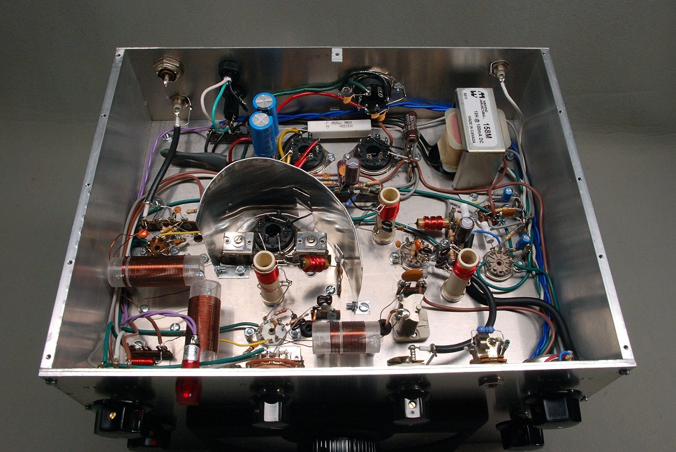
| RF Input: Our journey through the underside of the 6x2 receiver begins at the RF input. Vintage equipment typically uses either an SO-239 connector or an RCA phono connector, so this receiver is fitted with both SO-239 and RCA phono connectors at the input. These are in parallel and either can be used. The connectors are visible in the top left of the photo. The signal from the input runs via a coaxial cable to a terminal strip near the crystal calibrator which is just barely visible at the lower left in the photo. The line cord and fuse are visible on the back panel near the middle, and the accessory power socket is visible on the back panel on the right. A curved aluminum shield is used to isolate the mixer and crystal filter from the rest of the receiver. This shield is visible at the bottom right in the photo. |
 Click on the image for a larger view. Click here for a super detailed view. |
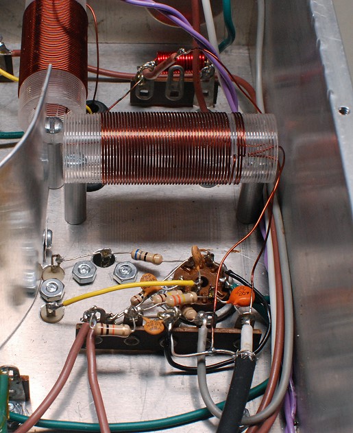
| Crystal Calibrator: A 6BA6 is used as a crystal calibrator in this receiver. The design is taken directly from the Drake R4A receiver. The crystal calibrator produces a 100 kHz (0.1 MHz) signal very rich in harmonics. These harmonics extend all the way up to 30 MHz and serve as marker signals every 0.1 MHz on the receiver dial. The calibrator can be trimmed so that its 50th harmonic is zero beat with WWV at 5 MHz. The calibrator is then accurate to about 2 parts in 5 million. The output of the calibrator is coupled through a 1.0 pf capacitor (orange, bottom right) to the signal coming from the RF input via a black coaxial cable (bottom right). From there the input signal and the signal from the crystal calibrator (if turned on) run to a three turn link on the input coil, visible above the tube socket in the photo. The input coil steps up the impedance from the low impedance of the antenna to the high impedance of the mixer input. The input coil is also tuned to the band in use by the band select capacitor on the top of the chassis. |
 Click on the image for a larger view. Click here for a super detailed view. |
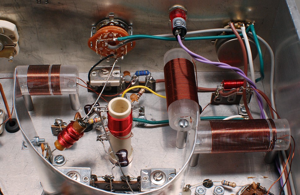
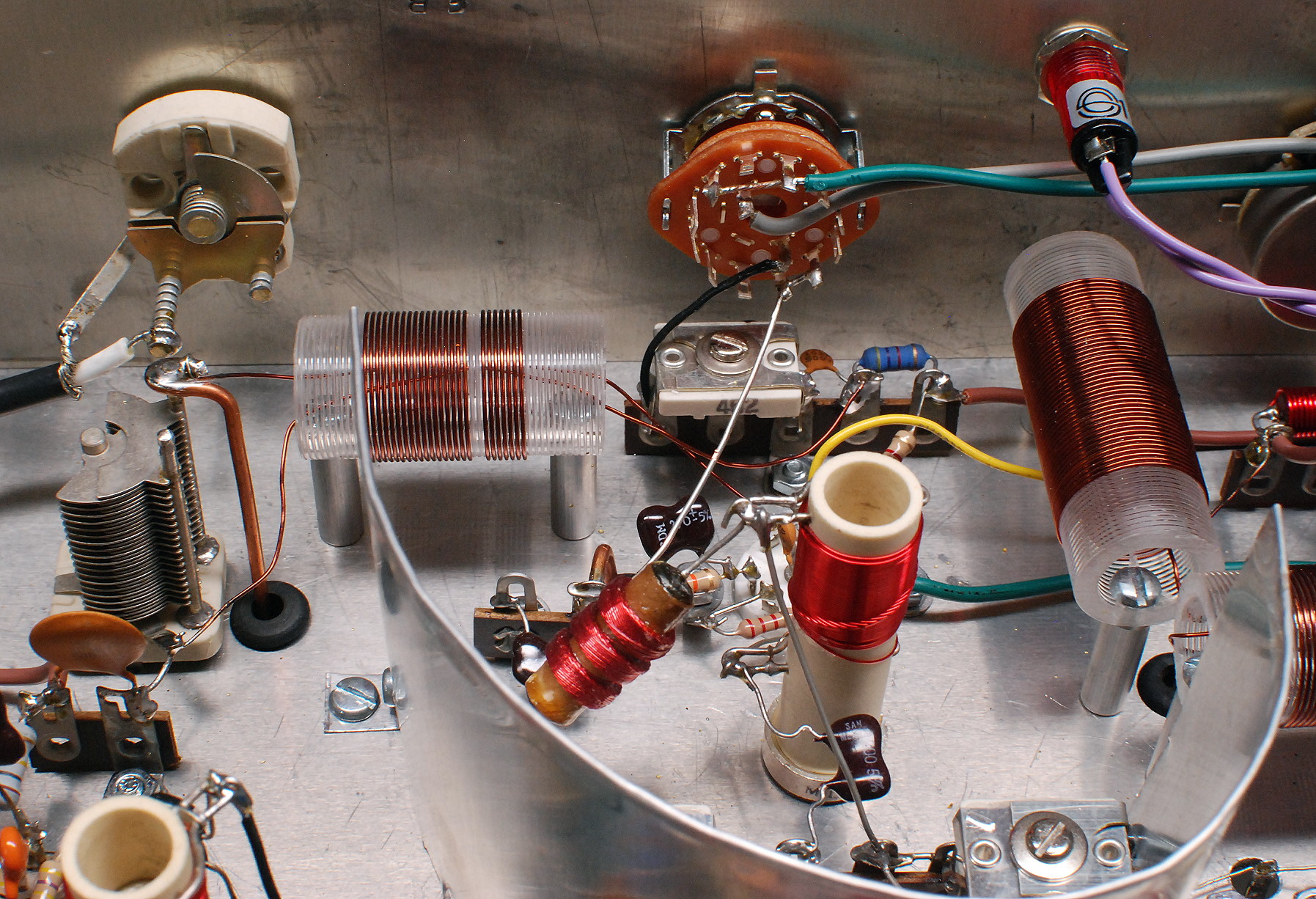
| Input Tuned Circuit and Mixer: The mixer is designed so that it will respond to signals in both the 80m and 40m bands at the same time, without any changes in the local oscillator. This greatly simplifies construction and results in a more stable local oscillator, but it requires a very selective tuned circuit at the input that can reject one band while passing the other. A single tuned circuit lacks the selectivity needed to reject the 40m band while passing the 80m band and vice versa, so two tuned circuits are used. These are tuned by the band select capacitor on the top side of the receiver. The two coils, visible at the right in the photo, are mounted at right angles to each other to prevent stray coupling between them, resulting in better overall selectivity. Also visible in this photo at the top on the front panel are, from left to right, the BFO frequency control (white), CALibrate/WWV control (orange), pilot lamp, and IF gain control. The mixer and local oscillator components are at center and left and will be discussed below. |
 Click on the image for a larger view. Click here for a super detailed view. |
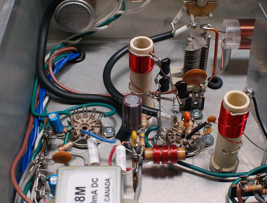
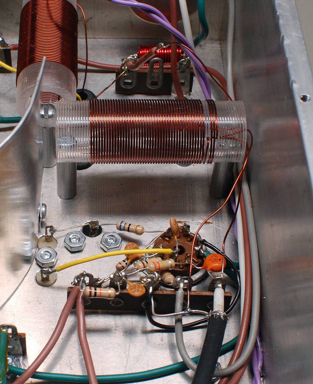
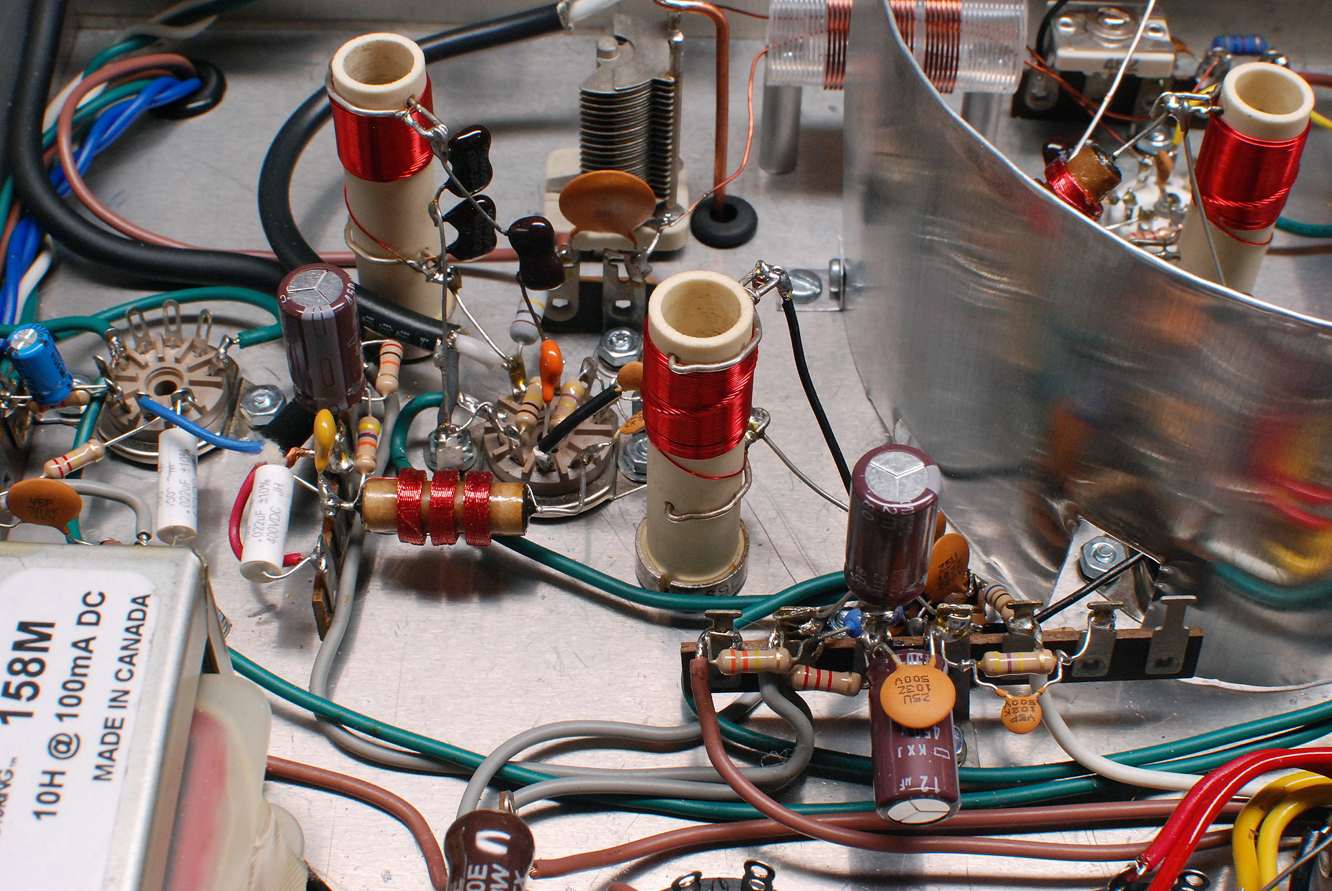
| Mixer and Local Oscillator: The 6x2 receiver uses an IF frequency of 1700 kHz. The local oscillator runs from 5200 kHz to 5500 kHz unless the WWV band is selected. Since the received frequency is equal to the local oscillator frequency plus or minus the IF frequency, the receiver will cover 3500kHz to 3800kHz in the 80m band and 6900 kHz to 7200 kHz in the 40m band without changing the range covered by the local oscillator. For WWV the local oscillator frequency is lowered to a range that includes 3300 kHz. A 6U8A is used as the mixer and local oscillator. The tube socket is visible just behind the red and white coil near the middle of the photo. The triode section of the 6U8A is used as the local oscillator. The local oscillator uses a circuit very much like a regenerative receiver, with a tickler feedback coil. The coil, which has two windings on it, can be seen in the left center of the photo. The capacitance for the oscillator is provided by a large 100 pf air trimmer capacitor visible at extreme left center, a fixed 68 pf mica capacitor, and the 35 pf main tuning capacitor on the top side of the receiver. The connection to the main tuning capacitor is via a stiff, heavy, copper wire that runs through a grommeted hole in the chassis. The wire can be seen attached to the 100 pf trimmer. See the Exterior Photos page for pictures of the main tuning capacitor. For reception of WWV, the orange CALibrate/WWV switch on the front panel (orange, top center in photo) switches in an extra fixed mica capacitor and mica compression trimmer capacitor (the white capacitor under the CALibrate/WWV switch). This lowers the frequency of the local oscillator to 3300 kHz so that WWV at 5000 kHz can be received. The local oscillator signal and output of the input tuned circuit (yellow wire) are fed into the pentode section of the 6U8A. The signals mix together and the original signals and their sum and difference (the desired 1700 kHz IF signal) appear at the output. The mixer output is fed to a resonant circuit consisting of a coil (red and white in photo) and capacitor that are tuned to 1700 kHz. These tune out all signals except the desired 1700 kHz IF signal. The IF signal is then sent to the crystal filter at the bottom of the photo. |
 Click on the image for a larger view. Click here for a super detailed view. |
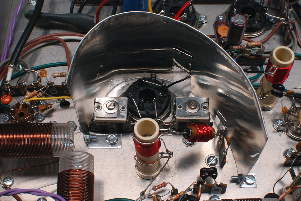
| Crystal Filter: The crystal filter gives the receiver its ultimate selectivity. The crystal is a 1700 kHz unit in an FT-243 holder. A 50 pf phasing capacitor is also used. The crystal and phasing capacitor are plugged into the octal socket on the top side of the receiver. See the Exterior Photos page for pictures of the crystal and phasing capacitor on the top of the chassis. In this photo the octal socket is in the center, and the two 480pf trimmer capacitors that are part of the crystal filter can be seen on either side of the octal socket. A capacitance meter is used to set these two capacitors to the same, maximum, capacitance. It is very important that these two capacitors be matched as closely as possible. The phasing capacitor on the top of the chassis is adjusted for the best selectivity. The red and white coil at bottom center is the mixer output coil. The other red and white coil, at the upper right, is the IF output coil. Since these are both tuned to the same frequency and are not shielded, they could couple together producing unwanted feedback. To prevent this, and to prevent any IF signal from leaking around the crystal filter, a curved aluminum shield is inserted between the crystal filter and the rest of the receiver. The IF signal passes through a small opening in the middle of the shield (small black wire) to the IF amplifier. |
 Click on the image for a larger view. Click here for a super detailed view. |
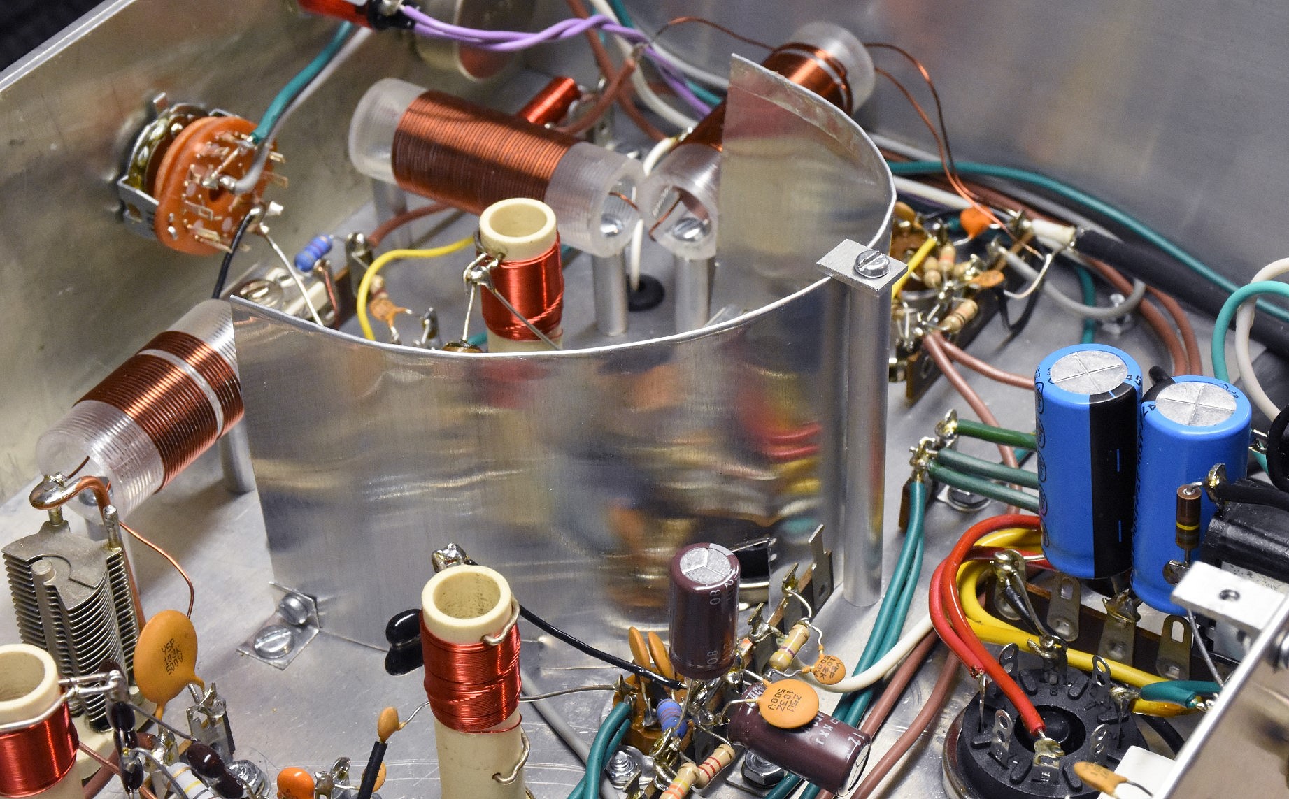
| Crystal Filter Shield Modification: The crystal filter shield was very effective in preventing undesired coupling between different parts of the receiver. However, as originally mounted, it could vibrate and modulate the high frequency oscillator, causing undesired microphonics. To eliminate the vibration, an aluminum post was mounted with a clamp on the end to hold the shield firmly in place, eliminating the microphonics. In this photo the post and clamp can be seen slightly to the right of center. |
 Click on the image for a larger view. Click here for a super detailed view. |
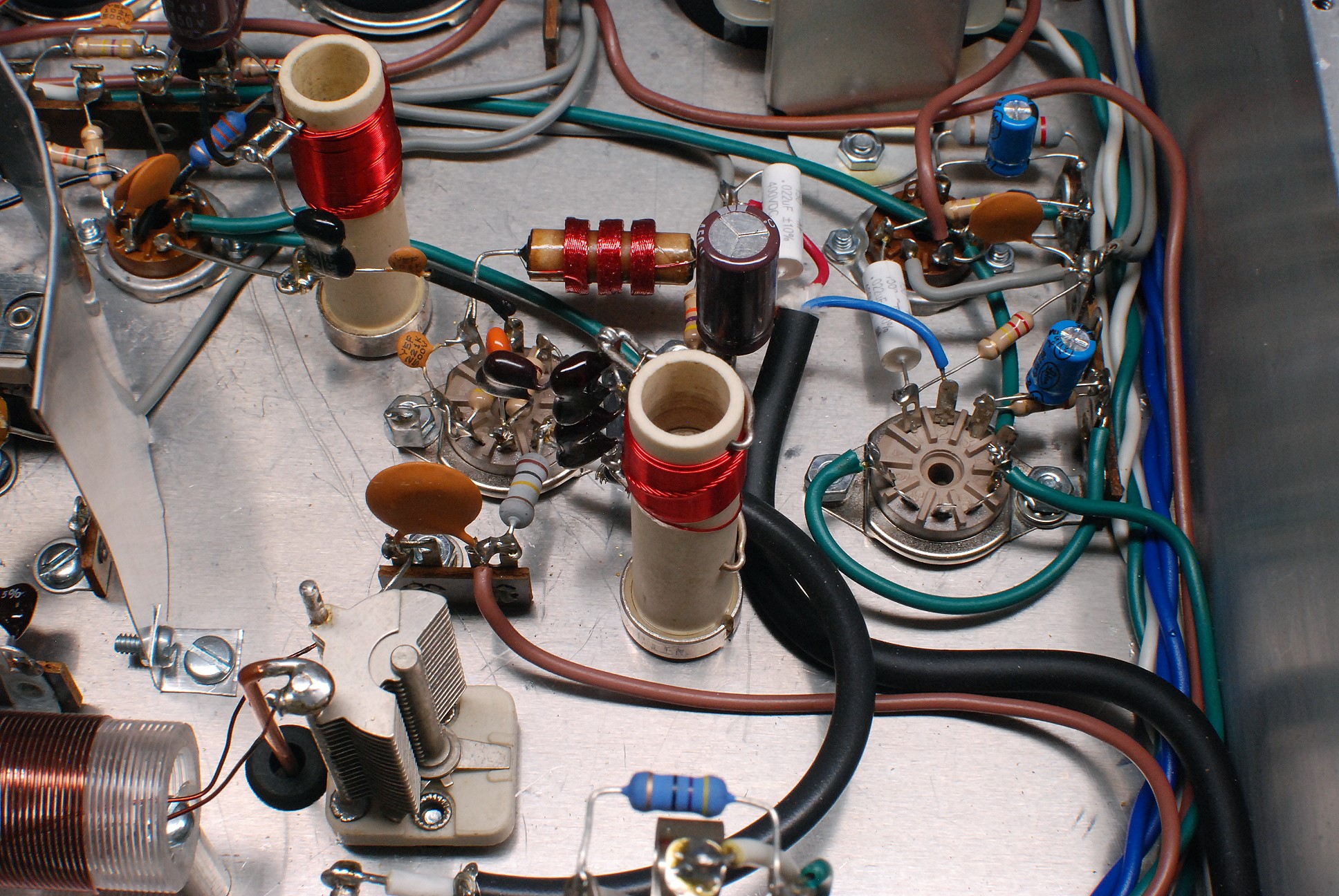
| IF Amplifier - Detector/BFO - Audio Amplifier: After passing through the crystal filter, the signal is fed into the IF amplifier, which is at the upper left in the photo. The IF amplifier uses a 6BA6 to amplify the IF signal by 6 dB to 31 dB, as determined by the setting of the IF gain control on the front panel. The IF amplifier can also be completely turned off by placing the receiver in standby mode. The output of the IF amplifier appears across the red and white coil at the upper left in the photo, and is then fed into the BFO/detector, which is in the middle of the photo. The BFO uses one triode of a 6CG7/6FQ7 to generate a signal at approximately 1700.7 kHz. The actual frequency is adjustable over several kHz by the BFO control on the front panel. The red and white coil in the center of the picture is used in the BFO, and is adjusted so that when the BFO control on the front panel is at the middle of its range the BFO oscillates at 1700.0 kHz exactly. The BFO control on the front panel is connected to the circuit via the large black coaxial cable on the left. The signal from the BFO and the output of the IF amplifier are fed into the other triode section of the 6CG7/6FQ7, which functions as a second mixer/detector. The signals mix together and their sum and difference appear at the output of the detector. In CW mode the difference is an audio tone at 0.7 kHz (700 Hz), which is easily separated from the RF signals at the output of the detector. In SSB mode the output is the recovered audio. The audio output of the detector passes out to the AF gain control on the front panel and back to the input of the audio preamplifier via the large shielded black cable on the right. The audio preamplifier uses one triode section of a 12AX7A. This is the 9-pin socket at center right in the photo. (The other section of the 12AX7A is not used.) After passing through the audio preamplifier the signal is then fed into a high quality audio power amplifier using a 6AQ5A power pentode, which is the 7-pin socket at the upper right in the photo. With a large, oversized, 10 watt audio output transformer, the 6AQ5A power amplifier easily develops over 4 watts of clean audio power. |
 Click on the image for a larger view. Click here for a super detailed view. |
| Receiver Mute Modification: When the receiver was first put on the air, it was found that the lack of AGC (Automatic Gain Control) made it impossible to use the receiver as a sending monitor. The overload and large audio output of the receiver during transmission were ear splitting and could not be tolerated. Simply disconnecting the speaker during transmission would not work because the audio power amplifier would then be without a load and could be damaged. What was needed was a mute circuit that operated in the IF amplifier, rather than the audio amplifier. The solution was to add a 180k resistor in series with the IF gain control during transmitting periods. The extra bias developed by the resistor cuts off the IF amplifier, muting the receiver during transmission. This technique was often used by Hallicrafters and other vintage receiver manufacturers. An RCA phono jack and SPST switch are connected in parallel with the resistor. If the switch is closed, the resistor is bypassed and the mute function is disabled. If the switch is opened, an external relay connected to the RCA jack can then control the muting of the receiver. The mute switch (black), resistor (Brown- Gray-Yellow), and RCA jack can be seen at top center in the photo. |
 Click on the image for a larger view. Click here for a super detailed view. |
| Detector/BFO - Audio Amplifier: In this photo, the BFO/detector is in the center and the audio section is on the right. You will notice that several pins on the front of the 9-pin socket on the right are not connected. This is because only one section of the 12AX7A is used. The large black cable on the right carries the audio from the detector output to the AF gain control on the front panel, and then back to the 12AX7A audio preamp. The large black coaxial cable on the left connects the BFO control on the front panel to the BFO circuit. (It was later found that the coaxial cable caused the BFO to drift and it was replaced with a simple copper wire. See "Modifications to the BFO" below.) The power supply choke is barely visible at the top right of the photo, along with the octal socket for the 0C3 VR tube. The local oscillator trim capacitor can also be seen in the photo at the lower left. |
 Click on the image for a larger view. Click here for a super detailed view. |
| Audio Preamplifier and Detector/BFO: This is a picture from the other side of the audio amplifier and detector, taken from the back of the receiver. The 6AQ5A audio amplifier socket is not visible because it is hidden behind the power supply choke at bottom left. The red RF choke in between the red and white coils is part of the circuit that removes any radio frequency energy from the output of the detector. The choke blocks the RF while permitting the audio to pass through. The AF gain control can just be seen at the left on the front panel at the back of the photo. To the right of the AF gain control on the front panel (at the upper right in the photo) is the BFO control, which is a very small variable capacitor. Just in front of the BFO control are the local oscillator trimmer capacitor and coil. The red and white coil at the lower right is the output of the IF amplifier. |
Click on the image for a larger view. Click here for a super detailed view. |
| Audio Preamplifier - Detector/BFO - IF Amplifier: In this photo, taken from the back of the receiver, the IF amplifier, BFO/detector, and audio preamplifier, can be seen from right to left. The mixer/local oscillator can be seen behind the metal shield at the upper right. The IF signal, after passing through the crystal filter, passes through an opening in the metal shield and is fed into the IF amplifier on the right. The terminal strip at the lower right contains part of the IF amplifier. The IF amplifier tube socket is behind the terminal strip and is hard to see in the photo. The output of the IF amplifier appears in the red and white coil in the middle of the photo. The 6CG7/6FQ7 detector/BFO tube socket is in the center of the photo. The red and white coil at the upper left is the BFO coil. The IF signal and BFO signal are fed into the detector/BFO, and the audio output passes through the red RF choke in the middle of the photo through a shielded cable to and from the AF gain control. The audio comes back from the AF gain control and is fed into the 12AX7A audio preamplifier on the left. It then passes to the audio power stage, which is behind the large power supply choke at the lower left and cannot be seen. |
 Click on the image for a larger view. Click here for a super detailed view. |
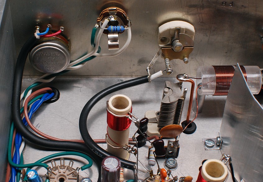
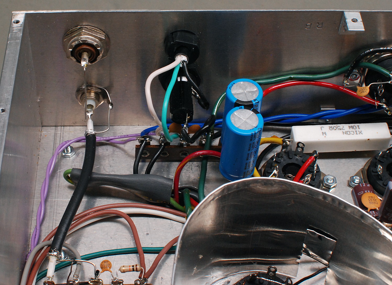
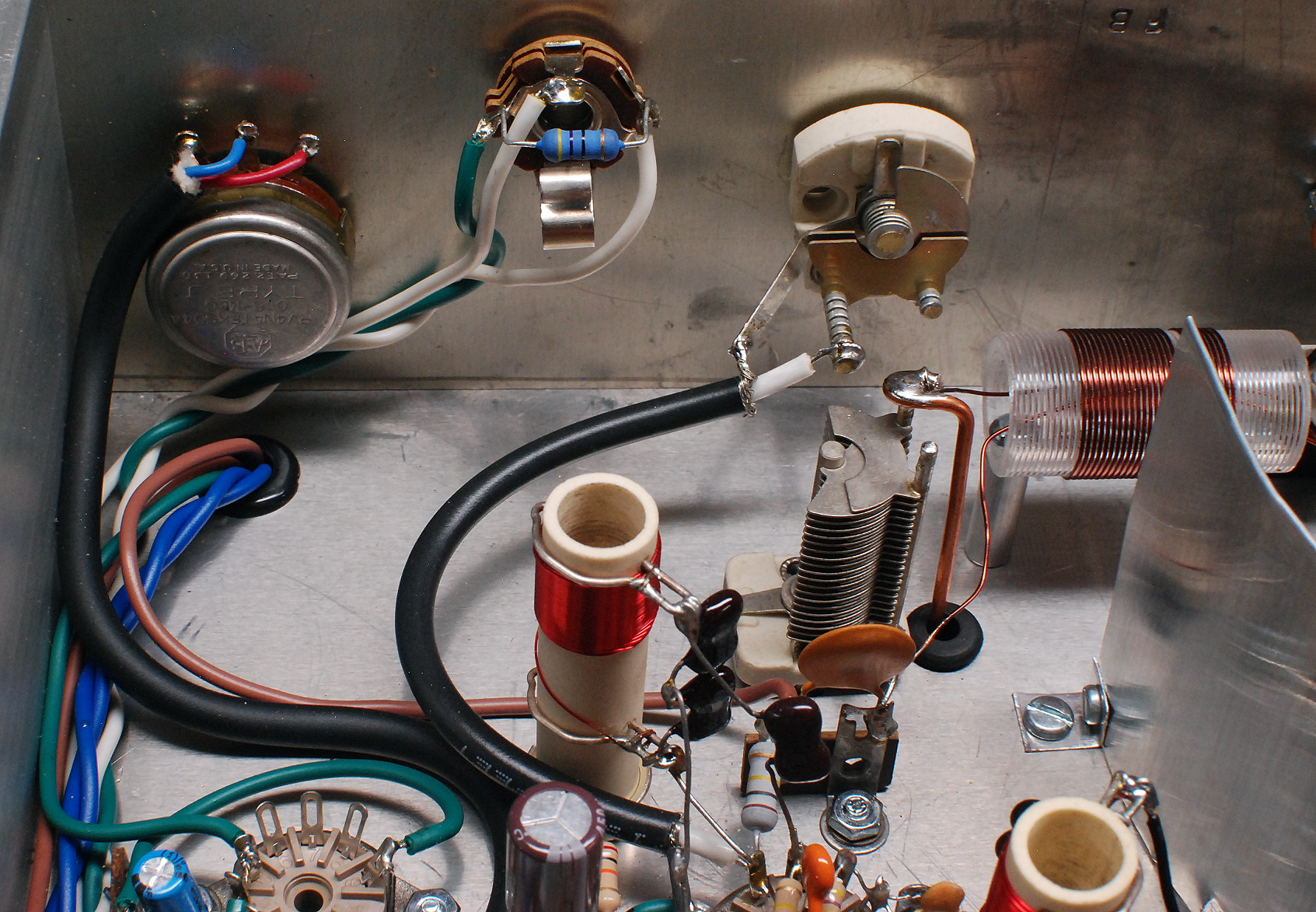
| Audio Gain - Phone Jack - BFO Frequency Adjust: The AF gain control, phone jack, and BFO control are mounted on the front panel, which is at the back of this picture. The AF gain control is on the left and is connected to the audio preamplifier and detector circuits via a 2-conductor shielded cable. The audio output from the output transformer is brought to the phone jack via white and green wires, and a second white wire carries the audio to the speaker jack on the back panel. Plugging headphones into the jack automatically disables the speaker. The BFO control (white) is a small value variable capacitor which adjusts the BFO frequency over a small range centered on 1700 kHz. It is connected to the BFO circuit via a piece of black RG-58U coaxial cable. (It was later found that the coaxial cable caused the BFO to drift and it was replaced with a simple copper wire. See "Modifications to the BFO" below.) The local oscillator trimmer capacitor and coil can be seen just in front of the BFO control. |
 Click on the image for a larger view. Click here for a super detailed view. |
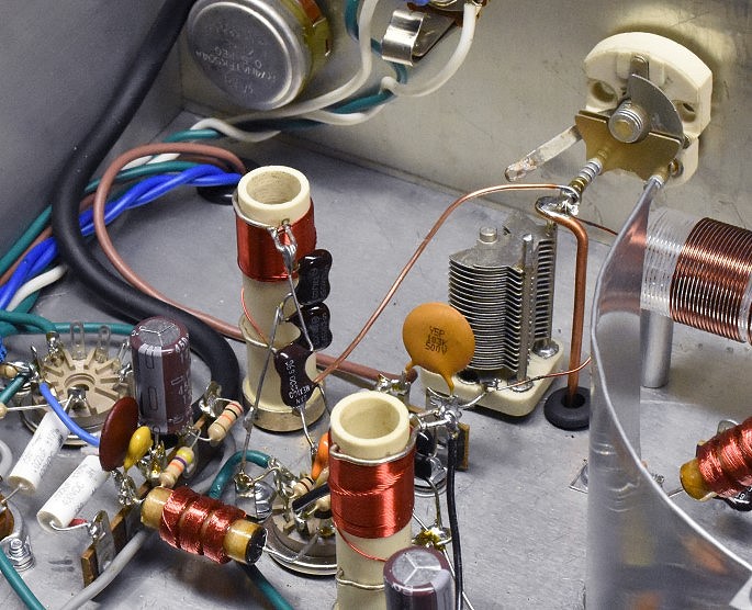
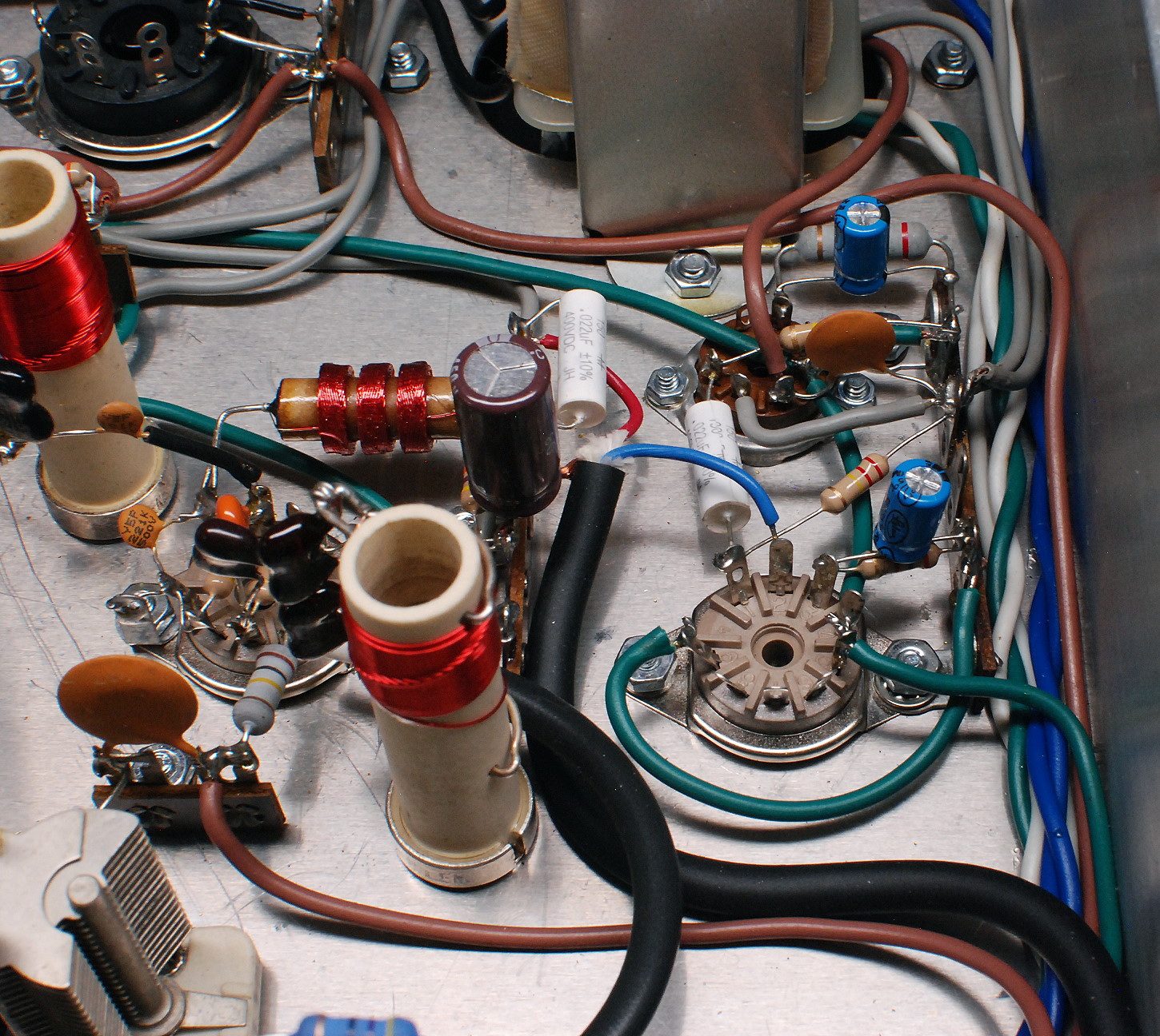
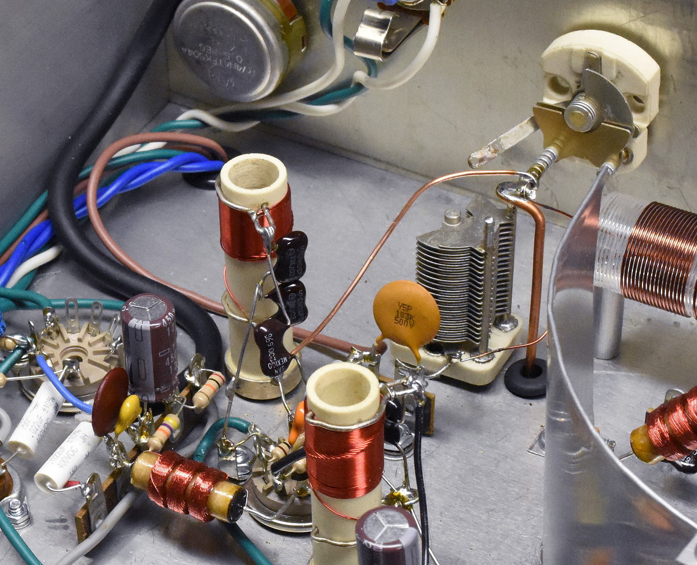
| Modifications to the BFO and Audio Detector: After the receiver was built it was found that the BFO drifted excessively. It took a while to track down the problem, but part of the source turned out to be the coaxial cable connecting the front panel BFO control to the BFO oscillator tube. The capacitance of the cable changed with temperature and altered the frequency of the BFO. When the coaxial cable was removed and replaced with a simple copper wire, the drift was reduced. To see the difference, note the connection to the white BFO trimmer capacitor at upper right in this photo and the one above. (Note: In this photo, the BFO capacitor and vertical HF oscillator trimmer capacitor look like they are connected together. This is due to the angle from which the photo was taken. They are not, in fact, connected together. Their separation can be clearly seen in the photo above.) The remainder/majority of the BFO drift was caused by the copper slug used in the coil and the position of the slug, which was just at the edge of the coil winding. Extra capacitance (about 110pf, not seen in this photo) was added across the complete coil winding (L8) and this placed the slug near the middle of the winding, rather than at the edge. (With a copper slug coil, the inductance goes down (and frequency goes up) as the slug is inserted in the coil.) This cured the drift and resulted in a stable BFO. After using the receiver for a while it was found that the audio frequency response of the receiver was too large. Excessive high frequency response allowed undesirable hiss and noise to reach the output of the receiver. To limit the high frequency response, the capacitance between the output of the detector and the input to the audio gain control was increased from 0.002 uf to 0.012 uf. This greatly reduced the noise and hiss while leaving the response between 300 Hz and 3 kHz unaffected. Rather than removing the original capacitor, an additional 0.01 uf capacitor (brown) was soldered in parallel with the original capacitor (yellow). The two capacitors can be seen next to each other, just to the left of the RF choke in the lower left corner of the photo. |
 Click on the image for a larger view. Click here for a super detailed view. |
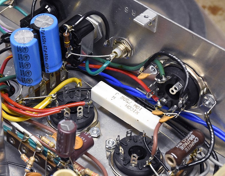
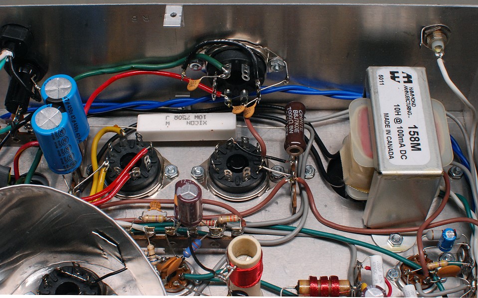
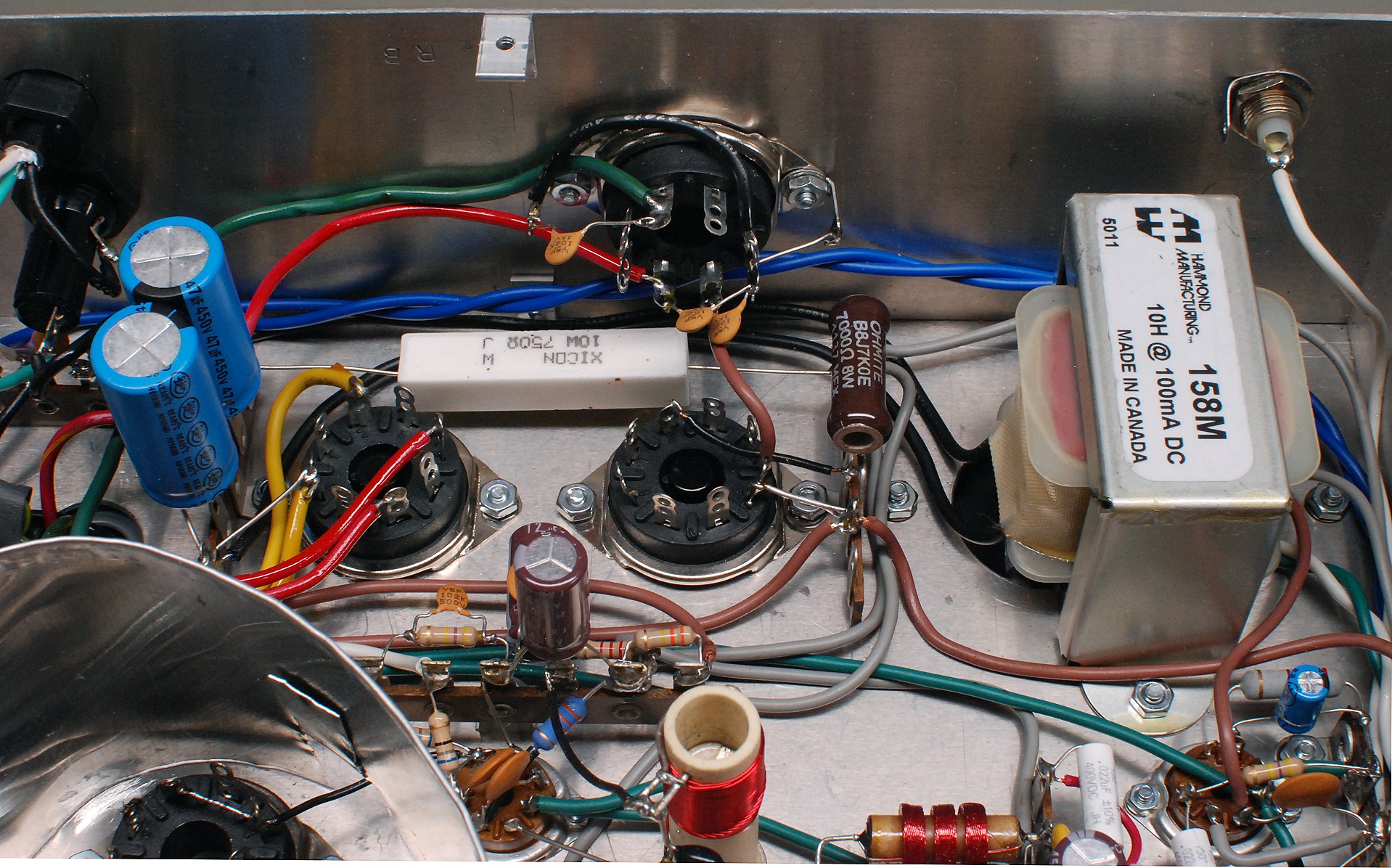
| Power Supply: The 6x2 receiver uses a power supply with a conventional, full wave, center tapped rectifier. A 5Y3-GT can easily handle the power needs of the receiver. The 5Y3-GT socket is the octal socket on the left. The yellow leads connect to the 5V filament winding of the power transformer, and the red leads connect to the high voltage winding of the power transformer. A capacitor input filter is used with a single 10 H power supply choke, which is visible on the right. The filter capacitors are the blue units on the left. A 750 ohm, 10 watt power resistor drops the output of the power supply to 250V under normal operating conditions. A 7 kohm 8 watt resistor and 0C3 VR tube (octal socket to the right of the 5Y3-GT socket) provide 108 volts regulated for the 6U8A local oscillator, 6U8A mixer screen grid, and 6CG7/6FQ7 BFO. An octal accessory jack on the back panel (top center in photo) allows the power supply to also power accessories that do not require much power, such as an electronic T/R switch, preamplifier, or frequency converter. At the bottom of the picture near the center the IF amplifier can be seen and the tube socket at the lower right is the 6AQ5A audio power amplifier. Connections to the audio output transformer are underneath the power supply choke on the right. The octal socket for the crystal filter is barely visible behind the metal shield at the lower left. |
 Click on the image for a larger view. Click here for a super detailed view. |
 Back to Dr. Greg Latta's
Electrical Engineering and Amateur Radio Pages
Back to Dr. Greg Latta's
Electrical Engineering and Amateur Radio Pages
 If you have any questions or
comments, you can send E-Mail to Dr. Greg Latta at
glatta@frostburg.edu
If you have any questions or
comments, you can send E-Mail to Dr. Greg Latta at
glatta@frostburg.edu