Click on the image for a super detailed view.
Important Safety Note: Working on or testing equipment such as the Heathkit HW-101 transceiver and the HP-23 power supply is extremely dangerous since very high voltages are present when the equipment is turned on, and may even be present when the equipment is turned off and unplugged. If at all possible, do all work with the equipment off and unpluggedand be sure that the capacitors are properly discharged before working on the equipment. The operator assumes all risk and liability in such matters! Do not work on this type of equipment unless you are experienced with working around very high voltages!
Some General Comments
On Alignment: Complete alignment instructions for the HW-101
can be found in the HW-101 manual.
However, the instructions in the manual can be confusing at times and often do
not explain the reason for the procedure that is being performed. Also, the
alignment instructions are based on technology typically available in the
1970s. With modern technology, such as frequency counters and inexpensive
digital voltmeters, some of the procedures are much easier.
The alignment instructions given here are an attempt to make the alignment a
bit easier by clarifying the procedure, using modern technology when possible,
and explaining the reason for each procedure.
Receiver Alignment:
Introduction To Receiver
Alignment:
Receivers contain many set-and-forget controls (coils, capacitors,
potentiometers, adjustable resistors etc.) that must be set to their proper
positions. As a result the receiver will exhibit maximum performance, which
includes things such as maximum stability, selectivity, sensitivity, and
accurate display of frequency. The process of making all of these
set-and-forget adjustments is called alignment.
S Meter
Adjustment:
In most situations, the S meter is used to indicate proper alignment, so it
must be set first.
The point of this adjustment is to have the S meter read zero on the 80m band
with a 50 ohm dummy load connected to the input and the RF gain set to its
maximum value.
To adjust the S meter, connect a 50 ohm dummy load (do not use a light
bulb!) to the antenna connector, then set the front panel controls as follows:
DRIVER PRESELECTOR - 12 o'clock position
MIC/CW LEVEL - fully counterclockwise
MODE - LSB
BAND - 3.5
MAIN TUNING DIAL (VFO) - 200
FUNCTION - PTT
RF GAIN - fully clockwise
METER - ALC
AF GAIN - 9 o'clock
Adjust the ZERO ADJ control (on the right side of the chassis) for a zero
indication on the meter.
Initial Heterodyne
Oscillator Coil Alignment:
The output of the heterodyne oscillator for each band must be set to the proper
level. An output that is too high is as bad as an output that is too low.
Adjustment of the heterodyne oscillator coils is perhaps the most
confusing/difficult of all the alignment adjustments. At this point we only do
an initial adjustment. Final adjustment is done
during transmitter alignment.
What Am I Measuring?:
During this adjustment, the bias on the heterodyne crystal oscillator V19A is
measured with a voltmeter. The bias is a direct measure of the oscillator
output, with a higher bias indicating higher output.
What Kind of Voltmeter Should I Use?:
Normally, a bias measurement such as this requires the use of a voltmeter with
a high (11 Mohm) input impedance. Most modern digital meters (even the cheap
ones from, for example, Harbor Freight Tools) meet this requirement, and it is
worth purchasing one if you do not already have such a meter. If absolutely
necessary an older analog meter with a sensitivity of at least 20,000 ohm/Volt
can be used. This is because a relatively low value 4.7 kohm resistor loads the
grid in this particular circuit.
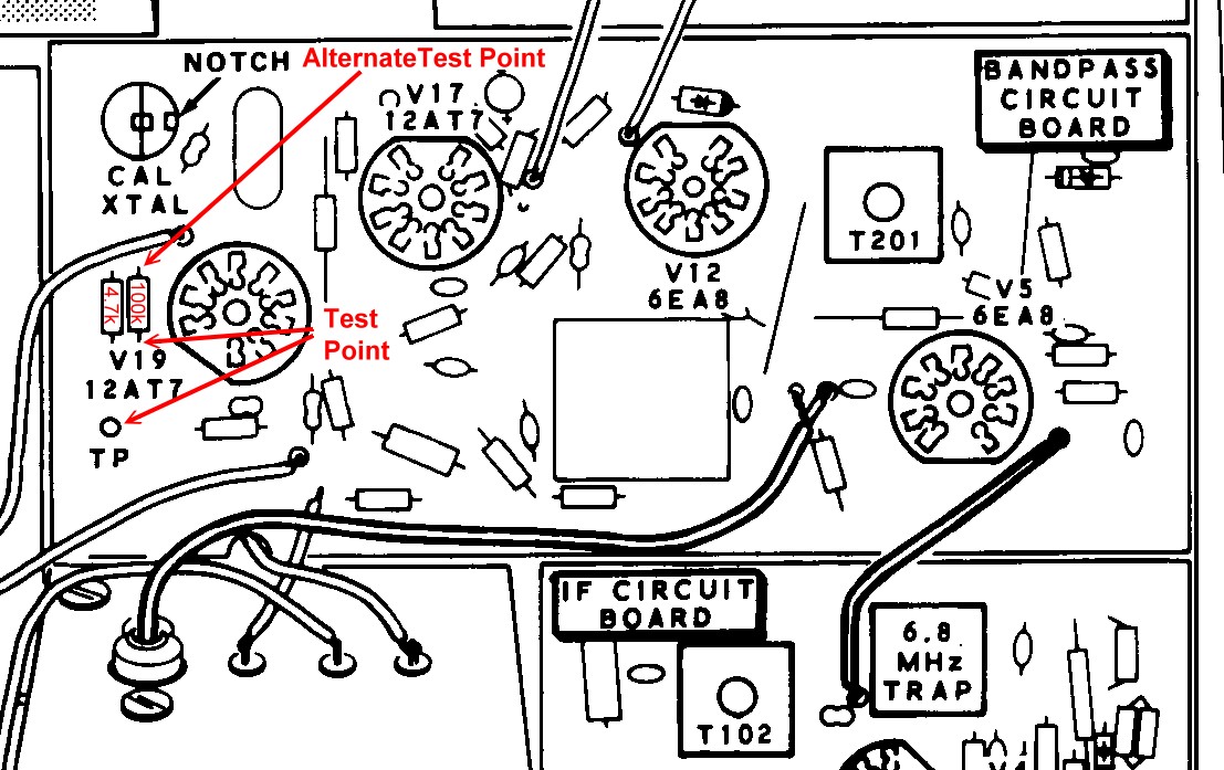
Where Do I Connect The Voltmeter:
One lead of the voltmeter is connected to ground. If you are using a digital
voltmeter, the negative lead goes to ground. If you are using an analog meter,
the positive lead is connected to ground. The other lead is connected to a test
point near V19 on the bandpass circuit board. Look at the bandpass circuit
board from the front and you will find V19 at top left just in front of the
tall crystal calibrator crystal. Immediately to the left of the V19 tube socket
you will see a 100 kohm (brown-black-yellow) resistor and a 4.7 kohm
(yellow-violet-red) resistor. The test point is in the front of these two
resistors and is labeled TP. If there is nothing but a hole where the test
point should be, simply connect to the 100 kohm resistor lead closest to you.
If your voltmeter reads 0V at TP, use the alternate test point, which is the
other end of the 100 kohm resistor. Click on the photo below to see where these
test points are located.
Test Point Locations for
Heterodyne Oscillator Coil Alignment
Click Here To Enlarge
What If The Coil Cover Prevents Some Of The Coils From Being
Adjusted?
The coils should be adjusted with the coil cover in place. If some of
the coils are blocked by the cover, as they were in my HW-101, the holes in the
cover must be enlarged. Click here to find out how to
modify the coil cover and enlarge the holes.
How Do I Make The Adjustment?:
Set the bandswitch to a particular band and locate the coil for that band. Then
make the adjustment by noting the following:
1. You do not necessarily want to adjust each coil for a maximum
reading. A reading that is too high is as bad as a reading that is too
low. What you want is a reading as high as possible between -0.5 V and
-2.0 V, but not exceeding -2.0 V.
2. For each coil you will find a setting that maximizes the reading. If this
reading is between -0.5 V and -2.0 V, then leave the coil set at the maximum
reading.
3. If the maximum reading is larger than -2.0 V, it must be reduced to -2.0 V.
From the peak value, turn the coil in both directions to find out in which
direction the value drops more slowly, then turn the coil in that direction
until the value drops to -2.0 V.
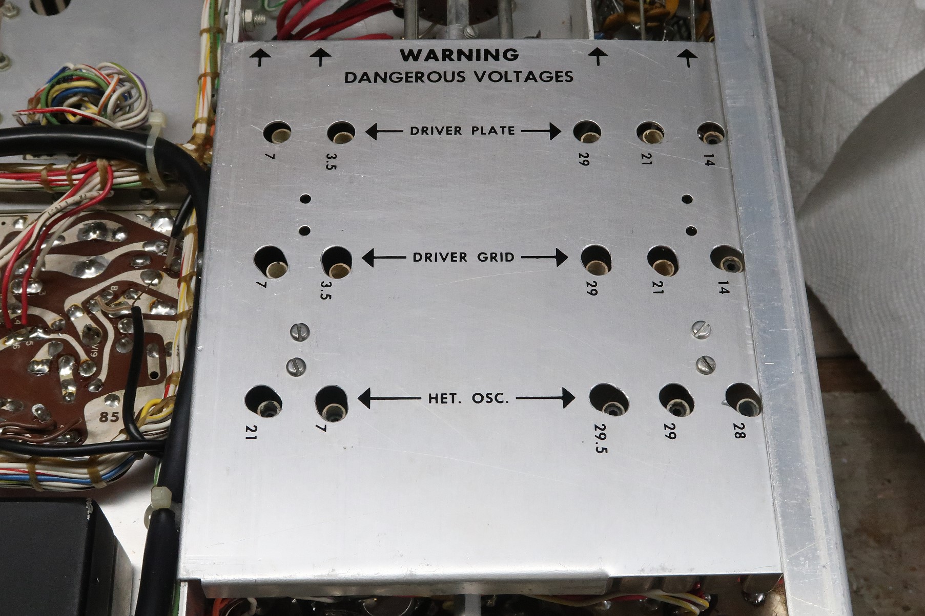
Where Are The Coils Located?:
This adjustment must be made for all eight heterodyne oscillator coils. Five of
the coils, 21 MHz, 7 MHz, 29.5 MHz, 29.0 MHz, and 28 MHz, are marked on the
coil cover and are accessed from the bottom of the chassis. The coils for 3.5
MHz, 14 MHz, and 28.5 MHz are marked and adjusted from the top side of the
RF-driver board as shown in the diagram below.
Location of the 3.5, 14, and 28.5
Heterodyne Oscillator Coils
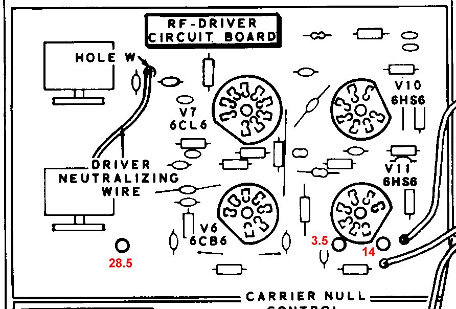
Click Here To Enlarge
Receiver IF
Alignment:
The receiver 3395 kHz IF section must be adjusted for maximum response at 3395
kHz.. This involves adjusting T201 on the bandpass circuit board and T102, and
T103 on the IF circuit board, as shown in the picture below.
Set the front panel controls as follows:
DRIVER PRESELECTOR - 12 o'clock position
MIC/CW LEVEL - fully counterclockwise
MODE - LSB
BAND - 3.5
MAIN TUNING DIAL (VFO) - 400
FUNCTION - PTT
RF GAIN - fully clockwise
METER - ALC
AF GAIN - 9 o'clock
Turn on the calibrator by setting the function switch to CAL and tune in the
calibrator signal for maximum response on the S meter.
When tuning in the calibrator signal, turn the DRIVER PRESELECTOR to make
sure there is a variation in volume. If there is no variation in volume the
signal is a spurious signal and NOT the calibrator signal.
Reset the DRIVER PRESELECTOR to the 12 o'clock position.
Adjust T201 for maximum S meter reading/maximum volume.
Adjust the top and bottom slugs of T102 for maximum S meter reading/maximum
volume. To adjust the bottom slug you must have an alignment tool that will
pass through the top slug and then fit into the bottom slug.
Adjust T103 for maximum S meter reading/maximum volume.
Touch up all three for maximum S meter reading/maximum volume.
Receiver IF Alignment
Location of T201, T102, and T103
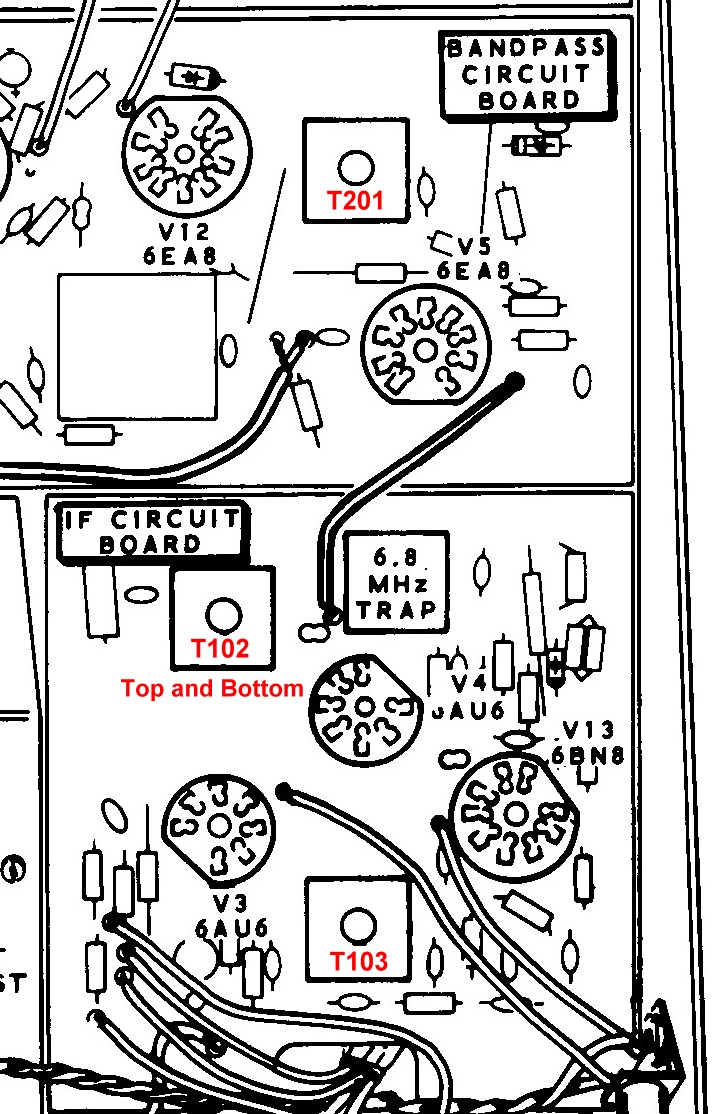
Click Here To Enlarge
General Comments On
Aligning An Analog Frequency Display:
In many receivers or transmitters a parallel resonant circuit (tuned circuit)
is coupled to an analog readout, typically a slide rule display or, as in the
HW-101, a rotary display. The tuned circuit usually consists of a variable
capacitor as the main controlling element in parallel with a coil that can be
adjusted and then left in place. A trimmer capacitor is also in parallel with
the variable capacitor, either mounted directly on the capacitor or as a
separate unit.
The goal in aligning such a system is to find the particular combination of
trimmer capacitor setting and coil setting that will cause the display to read
correctly at two different frequencies typically near the opposite ends of the
display (when adjusting a local oscillator), or for S meter readings to be
maximized at the calibration frequencies (when adjusting an RF amplifier).
Signals at the two desired frequencies must be available from a frequency
generator/synthesizer or a crystal calibrator.
It is important to note that in some cases, such as the HW-101, the actual
resonant frequency of the tuned circuit is lowest when the analog scale
indicates the highestfrequency! For example, in the HW-101, the VFO
frequency is lowest (5.000 MHz) when the main tuning is at 500, and highest
(5.500 MHz) when the main tuning is at 0. This apparent discrepancy occurs
because of the mixing scheme in use. Regardless, the frequency of the tuned
circuit is lowest when the variable capacitor is meshed, and highest when it is
unmeshed.
To align the system, an iterative procedure is used. The coil and trimmer
capacitor are adjusted a little bit each time, and the procedure is used over
and over again until the final settings are found.
Here is the general procedure:
1. Set the analog scale and the frequency generator to the calibration
frequency where the capacitor plates are more meshed.
Adjust the coil to tune in the calibration signal and/or maximize the S
meter reading.
2. Set the analog scale and the frequency generator to the calibration
frequency where the capacitor plates are less meshed.
Adjust the trimmer capacitor to tune in the calibration signal and/or
maximize the S meter reading.
3. Repeat this procedure over and over again until the calibration signals
appear at the correct positions on the analog scale.
It is usually necessary to repeat this procedure many times until the
calibration signals appear where they should on the analog scale or the S meter
readings are maximized. Sometimes the procedure can be sped up by going "a
little too far" with the trimmer capacitor on each run.
VFO Alignment:
Make sure the transceiver has warmed up for at least 30 minutes before making
the following adjustments.
Before aligning the VFO, read the previous section General Comments On Aligning An Analog Frequency
Display, keeping in mind that the HW-101 VFO is an oscillator and that the
VFO frequency goes down as the main tuning display goes up.
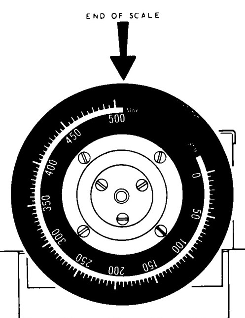
Before actually aligning the VFO, the rotary scale must be set properly on the
main tuning shaft. When the main tuning control is rotated counterclockwise as
far as it will go (do not force it) the scale should be positioned as shown in
the diagram below, with the end of the scale (the white bar) directly under the
indicator line.
The scale is connected to the main tuning shaft via a slip clutch. The scale
can be held in place by pressing and holding the Zero Set button. The main
tuning knob can then be turned to rotate the main tuning shaft while the scale
is held in place. This alters the position of the scale relative to the shaft.
To Align The Frequency Scale:
Rotate the main tuning dial counterclockwise until it stops. Do not force it.
If the end of the scale is too far to the right, back up the main tuning knob
until the reading is about 475. Press and hold Zero Set while you turn the main
tuning knob about 1/4 turn to the right (clockwise). Recheck the setting. If
still too far to the right, repeat the process until the scale is positioned
correctly.
If the scale is too far to the left, back up the main tuning dial until the
reading is about 475. Press and hold Zero Set while you turn the main tuning
knob about 1/4 turn to the left (counterclockwise). If still too far to the
left, repeat the process until the scale is positioned correctly.
Proper Position of Analog Scale When
Main Tuning Dial
Is Turned Counterclockwise As Far As It Will Go
Click Here To Enlarge
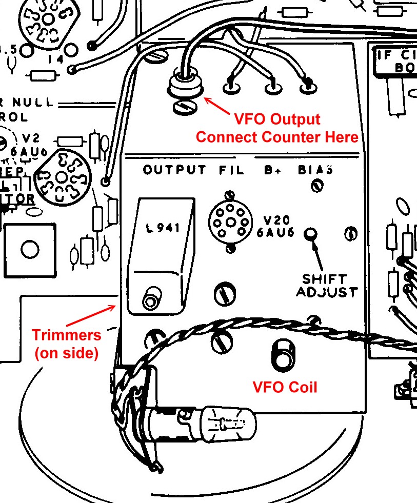
To Align The VFO Using A Frequency Counter:
Since the VFO is an oscillator that has a buffer stage to isolate it, the
easiest way to align the VFO is to use an accurate frequency counter. There is
an RCA connector on the rear of the VFO housing. Disconnect the cable currently
in the jack and connect the frequency counter to the jack. See the diagram
below to see where to connect the counter and for the location of the VFO
adjustments.
1. Turn the main tuning dial counterclockwise until it reads exactly 500.
Adjust the VFO coil so that the counter reads exactly 5000 kHz.
2. Rotate the main tuning dial clockwise until it reads exactly 0. Adjust the
trimmer capacitor(s) on the side of the VFO enclosure so that the counter reads
exactly 5500 kHz.
3. Reset the dial to 500 and readjust the VFO coil so the counter again reads
5000 kHz.
4. Reset the dial to 0 and adjust the trimmer(s) so that the counter again
reads 5500 kHz.
5. Repeat this procedure as many times as necessary until the counter reads
5000 kHz at the 500 mark and 5500 kHz at the 0 mark. This could take quite a
few repetitions. Sometimes the procedure can be sped up by going "a
little too far" with the trimmer capacitor on each run.
To Align The VFO Using The Crystal Calibrator:
Lacking a frequency counter, the transceiver crystal calibrator can be used.
For highest accuracy the crystal calibrator should be calibrated before
aligning the VFO. Crystal calibrator alignment is
explained in the transmitter alignment section. Note that the Heathkit manual
is not concerned with with prior calibration of the crystal calibrator, so this
step may not be necessary. See the diagram below for the location of the VFO
coil and the calibration trimmer capacitors.
1. Set up the transceiver to receive on the 3.5 MHz band.
2. Turn on the calibrator by setting the mode switch to CAL and find the
calibrator signal at the top end of the main tuning dial. This should be
somewhere above 475 on the dial.
3. Adjust the tuning for zero beat and, while carefully adjusting the VFO coil,
"walk" the calibrator signal until zero beat occurs at 500 on the
dial.
4. Rotate the tuning dial to the the bottom of the scale and find the
calibrator signal around 0 at the bottom of the scale. This should be somewhere
below 25 on the dial.
5. Adjust the tuning for zero beat and, while carefully adjusting the trimmer
capacitor(s), "walk" the calibrator signal until zero beat occurs at
0 on the dial.
6. Go back up to the top of the scale and find the calibrator signal around
500. Repeat step 3.
7. Go back to the bottom of the scale and find the calibrator signal around 0.
Repeat step 5.
8. Repeat this procedure until the calibrator signal is zero beat at the 0 mark
and the 500 mark. This could take quite a few repetitions.
Since it is possible, in an extreme case, to be 100 kHz off, it is a good idea
to tune in a signal of known frequency and make sure it comes in at the proper
place on the dial.
Location of VFO Adjustments and
Connections
Click Here To Enlarge
Driver Grid And Plate
Coil Alignment:
Make sure the transceiver has warmed up for at least 30 minutes before making
the following adjustments.
Though the driver grid and plate coils are used both by the receiver and the
transmitter, they are adjusted in receive mode. The adjustments are easy to
make. However, because of the circuit design, the adjustments interact with
each other . For example, changing the adjustment of the 21.0 MHz coils will
also affect the 14.0 MHz and 7.0 MHz bands. As a result, they must always be
adjusted in the proper order. This also means you can't just touch up
the coils for one band without redoing all of the others.
The 3.5 MHz coils are adjusted first, followed by the 29 MHz, 21 MHz, 14 MHz,
and 7 MHz coils. They must be adjusted in this order.
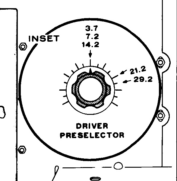
The actual frequencies used for adjustment are 3.7 MHz, 29.2 MHz, 21.2 MHz,
14.2 MHz, and 7.2 MHz. When adjusting any set of coils, the driver
preselector control must be set to the proper position as shown below:
Preselector Settings for
Driver Grid And Plate Coil Alignment
Click Here To Enlarge
Connect a 50 ohm dummy load to the transceiver antenna connector.
Set the front panel controls as follows:
DRIVER PRESELECTOR - 12 o'clock position
MIC/CW LEVEL - fully counterclockwise
MODE - LSB
BAND - 3.5
MAIN TUNING DIAL (VFO) - 200
FUNCTION - PTT
RF GAIN - fully clockwise
METER - ALC
AF GAIN - 9 o'clock
When tuning in any calibrator signal, turn the DRIVER PRESELECTOR to make
sure there is a variation in volume. If there is no variation in volume the
signal is a spurious signal and NOT the calibrator signal. When you are
finished verifying the calibrator signal, reset the DRIVER PRESELECTOR control
to the proper position as shown in the picture above.
Turn on the crystal calibrator by moving the function switch to CAL.
With the band selector in the 3.5 MHz position tune in the calibrator signal
near the 200 position on the main tuning dial. Adjust the main tuning dial for
a maximum S meter reading.
Be sure the DRIVER PRESELECTOR is in the 3.5 position as shown above and adjust
the coils marked 3.5 for maximum S meter reading.
Change the band selector to the 29.0 MHz position. Tune in the calibrator
signal near the 200 position on the main tuning dial and adjust for a maximum S
meter reading..
Be sure the DRIVER PRESELECTOR is in the 29.2 position as shown above and
adjust the coils marked 29 for a maximum S meter reading.
Change the band selector to the 21.0 MHz position. Tune in the calibrator
signal near the 200 position on the main tuning dial and adjust for a maximum S
meter reading..
Be sure the DRIVER PRESELECTOR is in the 21 position as shown above and adjust
the coils marked 21 for a maximum S meter reading.
Change the band selector to the 14.0 MHz position. Tune in the calibrator
signal near the 200 position on the main tuning dial and adjust for a maximum S
meter reading..
Be sure the DRIVER PRESELECTOR is in the 14 position as shown above and adjust
the coils marked 14 for a maximum S meter reading.
Change the band selector to the 7.0 MHz position. Tune in the calibrator signal
near the 200 position on the main tuning dial and adjust for a maximum S meter
reading..
Be sure the DRIVER PRESELECTOR is in the 7 position as shown above and adjust
the coils marked 7 for a maximum S meter reading.
Remember, these adjustments must always be done in sequence since they interact
with one another.
Transmitter Alignment:
Introduction To
Transmitter Alignment:
Because many receiver circuits are shared with the transmitter, you must
align the receiver first before aligning the transmitter.
When making any transmitter adjustments, be sure a 50 ohm dummy load (do NOT
use a light bulb) is connected to the transceiver.
Transmitter Bias
Adjustment:
The first transmitter adjustment is to set the bias on the final amplifier
tubes to the correct value. This is done by putting the transmitter in transmit
mode while in LSB mode with no drive on the final amplifier tubes and turning
the BIAS control (on the right side of the transceiver) so that the cathode
current reads the correct value.
Important Note: Placing the transmitter in transmit mode for more than a few
seconds with the bias at the wrong value can damage the final amplifier tubes.
Set the front panel controls as shown below:
DRIVER PRESELECTOR - 12 o'clock position
MIC/CW LEVEL - fully counterclockwise
FINAL (round knob) - to 10 o'clock
FINAL (lever knob) - to 4 o'clock
MODE - LSB
BAND - 3.5
MAIN TUNING DIAL (VFO) - 200
FUNCTION - PTT
METER - PLATE
Press the microphone button (or short the PTT pin on the microphone jack to
ground) and turn the bias control (on the right side) of the Transceiver to set
the meter needle at the "3" mark on the meter scale. There is an
arrow above the "3" on the meter scale to help identify the correct
setting.
Carrier Isolation Amplifier
Alignment:
In this step, transformer T1 at the output of the balanced modulator is
adjusted for maximum response.
Be sure a 50 ohm dummy load (do NOT use a light bulb) is connected to the
Transceiver.
Set the controls as shown above for Transmitter Bias
Adjustment and verify that the transmitter bias is set correctly.
then:
Set the METER switch to REL PWR and press the microphone button (or short the
PTT pin on the microphone jack to ground). The meter should read zero.
Set the MODE switch to the TUNE position and slowly turn the MIC/CW LEVEL
control clockwise until there is an indication of RF output of not more than 6
on the meter
Adjust the DRIVER PRESELECTOR and peak the RF output. Reduce the MIC/CW LEVEL
to keep the reading below 6.
Adjust the FINAL tune (round knob) and peak the RF output. Reduce the MIC/CW
LEVEL to keep the reading below 6.
Adjust the MIC/CW LEVEL control for an RF output of not more than 3 on the
meter.
Adjust transformer T1 for a maximum reading on the meter.
Readjust the MIC/CW LEVEL control for an RF output of not more than 3 on the
meter.
Again adjust transformer T1 on the modulator circuit board for a maximum
reading on the meter. See the diagram below.
Set the MODE switch back to LSB.
Location of T1
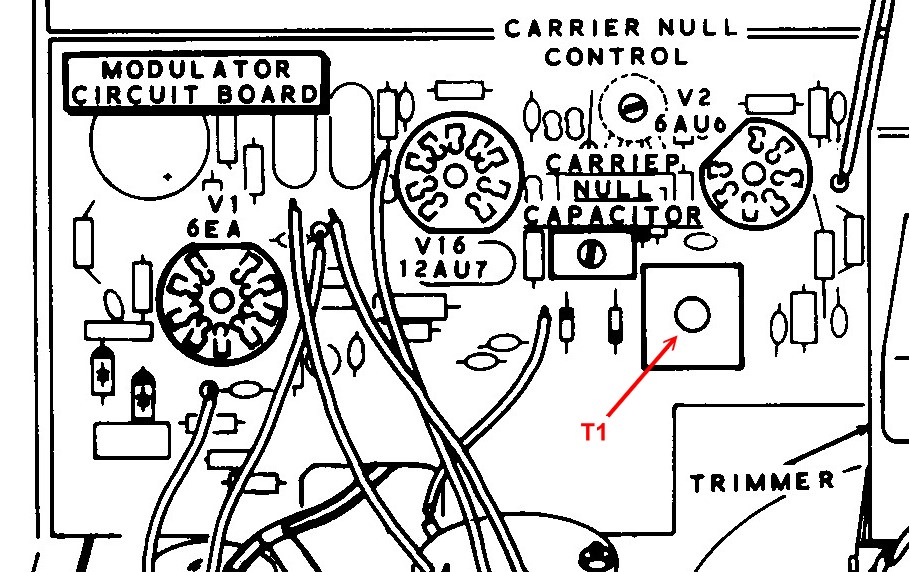
Click Here To Enlarge
Preliminary Final
Amplifier Neutralization:
Neutralization is one of the most important transmitter adjustments. If not
neutralized properly, the transmitter can break into self oscillation, causing
illegal spurious emissions and distortion.
Neutralization is required because unintentional/unavoidable positive feedback
through the tube being neutralized can cause it to self oscillate. To prevent
this self oscillation, some of the output is intentionally fed back to the
input out of phase to cancel the undesired positive feedback. Since the
amount of feedback needed varies with the particular tube(s) and the
surrounding circuitry, it must be done for every individual case. If the
tube(s) are changed or the circuit is rearranged, it must be redone.
For a power amplifier such as that in the HW-101, there is an easy way to tell
if the circuit is neutralized:
When the plate tuning (FINAL control on the HW-101) is adjusted, a dip
in the plate/cathode current will be observed. When looking at the RF output,
there will be a peak in the RF output.. When the dip in the
plate/cathode current occurs at the same setting of the FINAL control
where the peak in the RF output occurs, the amplifier is neutralized.
When making this adjustment, you can use the REL. POWER and PLATE positions of
the METER switch to read the output power and cathode current respectively.
This, however, requires constantly switching the meter from one position to
another. It is much easier to use an SWR meter or wattmeter connected to the
Transceiver output to read the RF output. The METER switch can then be left in
the PLATE position.
Theoretically, the neutralization should not depend on frequency, but in
reality it does. In this case, the final amplifier will initially be
neutralized at 3.5 MHz. Then, after neutralizing the driver stage, it will be
touched up at 14 MHz.
As a first step, Heathkit says to rotate the neutralizing capacitor fully
clockwise until resistance is felt, and then turn it counterclockwise one full
turn. But this is for a newly built HW-101. For an HW-101 that has been in
service, it is safe to assume that it is already near proper neutralization,
and to avoid this initial step.
Location
of Neutralizing Capacitor
and Driver Neutralizing Wire
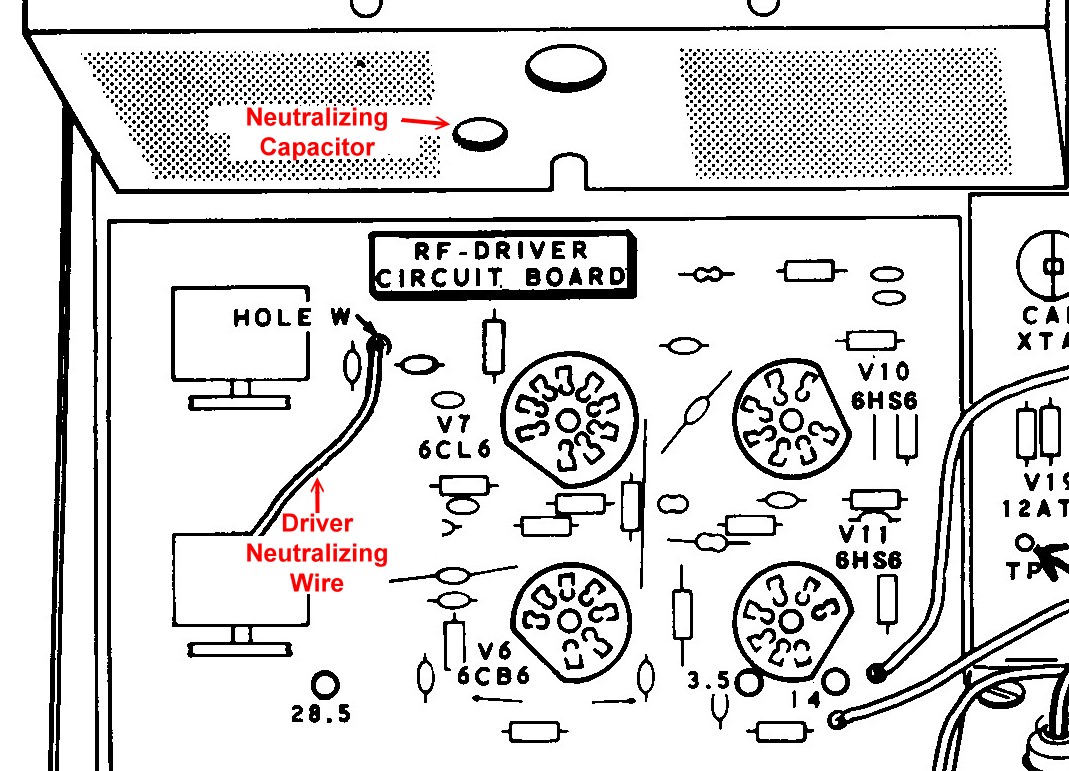
Click Here To Enlarge
The neutralizing capacitor is mounted on the front of the final amplifier
cage. See the figure above.
The following procedure may seem confusing, but once you do it a couple of
times you will understand the general idea.
When performing the following steps, keep the Transceiver at full power output
for the minimum time necessary. Then place the MODE switch at LSB and
let the final stage tubes cool for at least 30s before continuing.
To perform the initial neutralization:
1. Be sure the controls are set up as in the previous step,
Carrier Isolation Amplifier Alignment.
2. Turn the MODE switch to TUNE and adjust the MIC/CW LEVEL control and FINAL
tune control for maximum output (either on the REL. PWR meter or on the
SWR/wattmeter). Go back to LSB and allow the finals to cool. Carefully note
the position of the FINAL tune control.
3. Be sure the METER switch is set to PLATE, and activate TUNE again. While
TUNE is activated, move the FINAL tune control carefully back and forth about
the position noted earlier and verify that the plate current is at a minimum
in the same position as when the output is a maximum. Go back to LSB.
4 If maximum output and minimum plate current do not occur at the same setting
of the FINAL tuning control, make a mental note of how far they are apart on
the FINAL tuning control. Note the position of the neutralizing capacitor, then
rotate it a small amount (1/16 - 1/8 turn) clockwise and repeat the previous
steps 2 and 3.
5. If the maximum and minimum are farther apart on the FINAL tuning control,
you went the wrong way with the neutralizing capacitor. Return it to its
starting point and then go counterclockwise on the neutralizing capacitor. If
the maximum and minimum got closer together, rotate the neutralizing capacitor
a little further clockwise and recheck.
6. Continue the previous steps until you find the position of the neutralizing
capacitor where maximum output and minimum plate current occur at the same
setting of the FINAL tuning control.
Carrier Null
Adjustment:
The carrier null adjustment reduces the carrier in the output to the lowest
possible level. This is a compromise adjustment, because the best setting is
different for LSB and USB. A variety of indicators can be used to indicate the
carrier level in the output. These include the following:
1. An RF voltmeter connected to the output
2. An oscilloscope connected to the output
3. Listening to the output on a nearby receiver tuned to the carrier frequency
4. An RF wattmeter/SWR meter connected to the output
5. The REL. PWR meter on the HW-101
For best results, either an RF voltmeter, oscilloscope, or listening on a
receiver should be used. Lacking these, adequate results can be obtained using
the REL. PWR meter.
In all cases a 50 ohm dummy load (not a light bulb) must be connected to the
output. If you are using an RF voltmeter or oscilloscope, use a "T"
connector on the output so both the dummy load and voltmeter or oscilloscope
are connected at the same time. If you are using a receiver, do NOT connect it
to the output!
:
1. Tune the transceiver up on the 80m band at 3700 kHz.
2. Set the controls as follows:
METER - REL. PWR
FUNCTION - PTT
MODE - LSB
MIC/CW LEVEL - fully counterclockwise.
3. Activate PTT and adjust the carrier null control for minimum RF
output.
4. Adjust the carrier null capacitor for minimum RF output.
5. Switch to USB and repeat steps 3 and 4.
6. Repeat the above steps until the RF output is about the same both in LSB and
USB. This is a compromise. You want minimum RF output, but you want it to be
the same on LSB and USB.
See the diagram below for the location of the carrier null control and carrier
null capacitor.
Location
of Carrier Null Control
and Carrier Null Capacitor
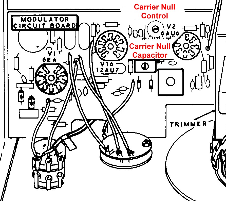
Click Here To Enlarge
Final Heterodyne
Oscillator Coil Alignment:
Before you perform this step, be sure you have done the initial heterodyne oscillator alignment.
Be sure a 50 ohm dummy load (do not use a light bulb) is connected to the
transceiver.
To perform the final heterodyne oscillator coil alignment:
1. Set the METER switch to REL. PWR
2. Set the BAND switch to 3.5 and the MAIN TUNING dial to 200 (3700 kHz).
3. Tune up the transceiver on 3700 kHz for maximum output as indicated on the
meter.
3. Switch the MODE switch to TUNE and use the MIC/CW LEVEL control to obtain a
reading between 3 and 9 on the meter.
4. Adjust heterodyne oscillator coil 3.5 for maximum output.
5. Repeat the following adjustment for each position of the BAND switch, except
adjust the coil with the same number as the BAND switch. Five of the coils, 21
MHz, 7 MHz, 29.5 MHz, 29.0 MHz, and 28 MHz, are marked on the coil cover and
are accessed from the bottom of the chassis. The coils for 3.5 MHz, 14 MHz, and
28.5 MHz are marked and adjusted from the top side of the RF driver board.
Driver
Neutralization:
In the HW-101, the driver stage must also be neutralized. The neutralizing
capacitor is a white wire attached to the frame of the front driver preselector
capacitor that runs through a hole in the RF Driver circuit board. For the
location of the wire, see the figure under
preliminary final amplifier neutralization. Note that the frame of this
capacitor is not directly grounded. Rather, it is connected to ground
through a 100 ohm resistor. When the white wire is inserted through the circuit
board, the wire is near the plate lead of the 6CL6 driver tube. The capacitance
between the two forms the driver neutralizing capacitor, and it is adjusted by
varying the amount of wire stuck through the hole. Inserting more wire through
the hole increases the capacitance. Pulling the wire out decreases the
capacitance. Crude, but it works.
It is not possible to monitor the output of the driver or the driver plate
current, so proper neutralization must be determined differently than in the
case of the final amplifier. For the driver, proper neutralization is indicated
by the lack of erratic behavior when the DRIVER PRESELECTOR is adjusted.
To neutralize the driver:
Set the BAND switch to 21.0 MHz
Set the MAIN TUNING to read 21.2 MHz
Go into TUNE mode and adjust the DRIVER PRESELECTOR, FINAL TUNE, and LOAD
controls for maximum RF output.
Turn the DRIVER PRESELECTOR control back and forth to see if this produces a
smooth peaking in RF output.
If turning the DRIVER PRESELECTOR control causes ragged or uneven changes in
the RF output, readjust the position of, or bend, the free end of the
driver neutralizing wire to produce a smooth
peaking in the RF output.
Final Amplifier
Neutralization Touch Up:
Repeat the preliminary final amplifier
neutralization, except perform the procedure at 14.2 MHz, where the
adjustment is more sensitive.
Crystal Calibrator
Alignment:
In this adjustment, the crystal calibrator is set to a frequency of exactly
100,000.0 Hz. You might be tempted to use a frequency counter to make this
adjustment, but unless the counter is a laboratory quality instrument with a
resolution of 0.1 Hz or 0.01 Hz it will not be accurate enough. The calibrator
frequency must be accurate within a fraction of a Hz. This is most
easily done be comparing a high harmonic of the calibrator signal to another
signal of known frequency, for example WWV. You will need a receiver capable of
receiving WWV at 10 MHz or 15 MHz.
To calibrate the crystal calibrator:
1. Use your receiver to tune in WWV at 10 MHz or 15 MHz. This may be possible
only at certain times of the day.
2. Be sure that the MIC/CW LEVEL control is fully counterclockwise so
there is no way the transmitter can put out any signal.
3. Connect a random length of wire from the transceiver output to the external
receiver antenna.
4. Tune the external receiver to WWV at 10 MHz or 15 MHz.
5. Set the FUNCTION switch to CAL and carefully adjust the CAL CRYSTAL
capacitor on the bandpass circuit board to zero beat the calibrate signal with
the WWV signal. The location of the Cal Crystal capacitor is shown in the
diagram below. Wait until there is no modulation present on WWV to make this
adjustment. Listen very carefully. When you get close to the proper adjustment
you will hear the noise in the background pulsate. Try to get the pulsation to
stop if possible. If you can't get it to stop, just get it to go as slow as
possible.
Location of
Crystal
Calibrator Adjustment
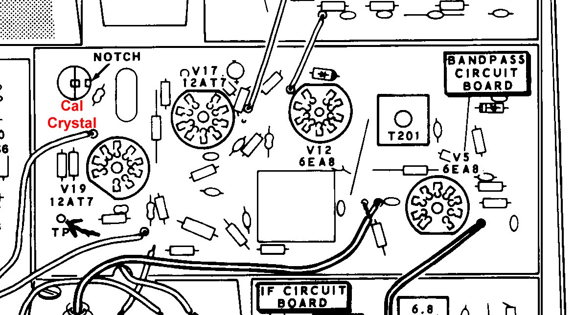
Click Here To Enlarge
VFO Shifter
Adjustment:
When switching from LSB to USB, the carrier oscillator frequency is changed.
This will cause the reading of the MAIN TUNING dial to read incorrectly unless
the VFO is also shifted when changing from LSB to USB. This is accomplished be
electronically switching a trimmer capacitor in and out when changing from LSB
to USB. This capacitor is mounted on the top side of the VFO enclosure.
Do NOT confuse it with the trimmer capacitors on the left side of the
enclosure.
To adjust the shift capacitor:
1. Adjust the MAIN TUNING dial to 200 kHz and the BAND switch to 3.5.
2. Set the FUNCTION switch to CAL to turn on the crystal calibrator.
3. Turn the MODE switch to USB.
4. Carefully zero beat the calibrator signal. Use the MAIN TUNING dial and peak
the DRIVER/PRESELECTOR control.
5. Set the MODE switch to LSB. Be careful not to touch the MAIN TUNING dial.
Note that the calibrator signal may or may not be zero beat in the LSB
position.
6. Turn the SHIFT ADJUST on the top of the VFO for an exact zero beat in the
LSB mode. See the diagram below for the location of the shift adjust capacitor.
7. Recheck for zero beat in the USB mode and repeat the adjustment until you
have zero beat in both LSB and USB at the same setting of the MAIN
TUNING dial.
Location
of VFO Shift Adjust Capacitor
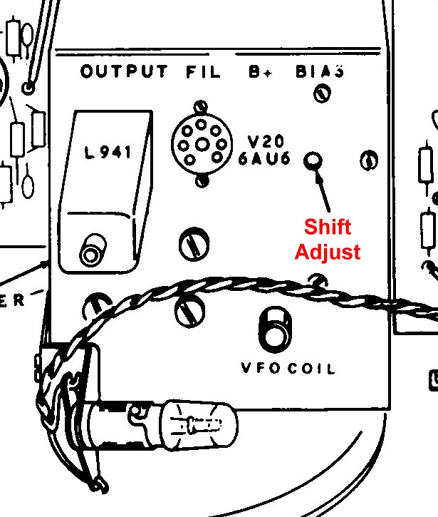
Click Here To Enlarge
 Back to Dr. Greg Latta's
Electrical Engineering and Amateur Radio Pages
Back to Dr. Greg Latta's
Electrical Engineering and Amateur Radio Pages
 If you have any questions or
comments, you can send E-Mail to Dr. Greg Latta at
glatta@frostburg.edu
If you have any questions or
comments, you can send E-Mail to Dr. Greg Latta at
glatta@frostburg.edu