
Click on the image for a super detailed view.
Important Safety Note: Working on or testing equipment such as the Heathkit HW-101 transceiver and the HP-23 power supply is extremely dangerous since very high voltages are present when the equipment is turned on, and may even be present when the equipment is turned off and unplugged. If at all possible, do all work with the equipment off and unpluggedand be sure that the capacitors are properly discharged before working on the equipment. The operator assumes all risk and liability in such matters! Do not work on this type of equipment unless you are experienced with working around very high voltages!
Introduction:
After the HP-23 power supply was restored I began work on the HW-101
transceiver. The tubes were removed, noting which particular tube came from
which particular socket, since the HW-101 has multiple 6EA8, 6AU6, 6HS6,
and 12AT7 tubes. This guarantees that each tube goes back into the same
socket it came from. Alignment sometimes depends on a particular tube, and
making sure each tube goes back into the same socket guarantees that the
alignment is not affected. The transceiver was then thoroughly checked for any
stray material on the circuits boards. A vacuum cleaner and clean camel hair
chip brush were used to draw out any dirt and foreign material. Gentle
compressed air was also used to blow out any foreign materials that might still
remain. Everything was carefully inspected for bad solder joints or broken
connections. None were found.
All of the controls were rather stiff and were carefully cleaned with Caig
DeoxIT. This loosened up the RF Gain, AF Gain, and MIC/CW controls. The
Function and Meter switches were quite tight. These were sprayed with DeoxIT
and then carefully worked free. After treatment they performed as they normally
should. Since the bandswitch was covered with an aluminum panel, it was left
for later cleaning.
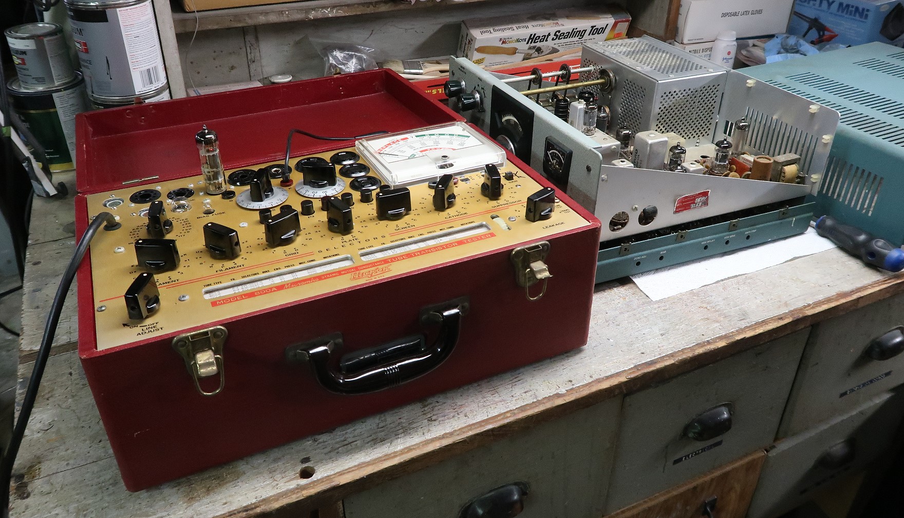
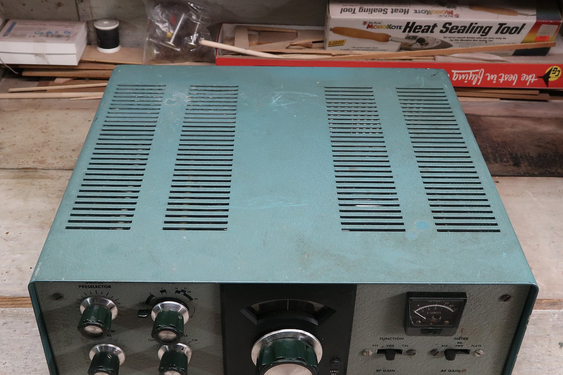
| Tube Testing: All of the tubes were tested on my Hickok 800A tube tester. This tester actually loads down the tube under test and measures its amplifying ability. All of the tubes tested fine except for the 6BN8, which was a little on the weak side but will probably work fine. The RCA 6146 finals tested fine, but the only real test for a final tube is to place it in actual service. In this picture you can also see the top cover on the right. It is in good shape. It just needs a really thorough cleaning. |
 Click on the image for a super detailed view. |
Initial Turn-On:
In April of 2022, after a thorough inspection and initial cleaning, the HW-101
was hooked up to the restored HP-23 power supply, and a speaker and crude
antenna were connected. The power supply was plugged into a VARIAC and then the
voltage was brought up very slowly while carefully observing the transceiver
for any overheating, smells, or other problems. None were observed. The voltage
was slowly brought up to 100%, and all was fine. Noise was heard from the
speaker, and the receiver appeared to be operating. Several strong signals
could be tuned in on 40m. After many, many years the HW-101 was coming alive!
Electrolytic Capacitor
Replacement:
There are surprisingly few electrolytic capacitors in the HW-101. They are the
following:
C2 - 10uf/15V cathode bias capacitor in the speech amplifier
C12 - 20uf/350V decoupling capacitor in the speech amplifier
C212 - 10uf/15V - cathode bias capacitor in the VOX amplifier
C304 - 20uf/350V decoupling capacitor in the audio power amplifier
C906 - 10uf/150V bias filter capacitor
These were all checked out with a capacitor tester and measured OK. However,
for a piece of equipment that is 50 years old it is standard procedure to
replace all electrolytic capacitors. They may initially be OK, but when placed
back in service the heat can cause them to dry out and fail. I ordered
replacement parts from Mouser Electronics at the same time I ordered new parts
for the HP-23 power supply. A list of the capacitors I ordered and their part
numbers is shown below.
| Description | Link | Source |
| Decoupling Capacitors C12 and C304: | ||
| 22uf 350V Electrolytic Capacitor - 2 Required (Replace 20uf with 22uF) |
598-226TXK350M | Mouser Electronics |
| Bias Filter Capacitor C906: | ||
| 10uf 150V Electrolytic Capacitor - 1 Required (Replace 150V with 160V) |
667-ECA-2CHG100 | Mouser Electronics |
| Cathode Bias Capacitors C2 and C212: | ||
| 10uF 15V Electrolytic Capacitor - 2 Required (Replace 15V with 16V) I had these on hand, but the part listed should do nicely. |
710-860160372001 | Mouser Electronics |
Some General Comments On
Replacing Electrolytic Capacitors:
Electrolytic capacitors contain an electrolyte that can dry out over the years.
They can still test and function fine if they contain only a fraction of the
electrolyte. When a vintage radio is first brought back on line the
electrolytic capacitors may function fine at first. However, after some use the
heat from the equipment may dry out what is left of the electrolyte and then
they fail.
In the long run, it is best to eventually replace all of the
electrolytic capacitors (called "recapping") in a piece of vintage
equipment. The needed capacitors can all be purchased and installed at the same
time. This saves shipping costs and avoids having to open up the equipment
multiple times.
To obtain a high enough voltage rating power supply capacitors may have to be
replaced with multiple identical units in series with appropriate equalizing
resistors across each. For power supply capacitors a higher capacitance and/or
voltage rating is OK.
For electrolytic capacitors in speech amplifiers and audio circuits the
capacitance should not be changed, since this could alter the frequency
response. However, a higher voltage rating is OK.
"Can" capacitors and other units containing several capacitors are
very hard to find (or are very expensive) and can be replaced with individual
units. However, for can capacitors, disconnect the bad unit but leave
it in place for aesthetic purposes.
Crystal Calibrator Repair:
After the initial turn-on it was found that the crystal calibrator did not work
properly. Turning on the calibrator caused the receiver noise to rise to a very
high level and the transceiver would go into transmit mode unless the ANTI-VOX
control was turned all the way down. One lead of diode CR201 was unsoldered to
disconnect the crystal calibrator output from the receiver input. This did
not solve the problem. All of the components in the calibrator circuit,
except for the crystal, were tested and found to be fine. Finally, a crystal
from another HW-101 that was used for parts was installed. This cured the
problem.
The crystal was bad, generating so much noise in the circuit that the noise
travelled down the B+ line to the heterodyne oscillator circuit, which was very
close by, where it got into the receiver. The strong noise overloaded the
ANTI-VOX circuit, causing it to do the exact opposite of what it should do,
putting the transceiver in transmit mode!
Carrier Oscillator Repair:
While using the receiver, it was found that the receiver had much lower
gain/sensitivity in the USB/CW mode than in the LSB mode. I suspected that
there was something wrong in the carrier oscillator circuit. Testing the output
of the carrier oscillator with an RF voltmeter probe connected to pin 3 of V16
showed about 3V of RF in LSB but only 0.5V in USB/CW. Also, the plate voltage
on V16A was found to be only 35V in USB/CW. Resistance checks of the V16A
circuit showed that plate resistor R6 had increased in value from 33k to 330k.
It was also found that the other plate resistor, R7, had increased in value
from 33k to 42k. Both resistors were replaced, and the receiver really came
alive. Problem solved!
Preselector Tuning Drum Repair:
One of the weaknesses of the HW-101 is the method used to attach the metal
pulleys to the preselector shaft. These were to be soldered to the preselector
shaft, but most builders did not have a large enough soldering iron to do the
job properly. As a result, the drums often come loose.
As shown in the sequence below, a better solution is to use epoxy glue to hold
the drums in place.
 Click on the image for a super detailed view. |
 Click on the image for a super detailed view. |
 Click on the image for a super detailed view. |
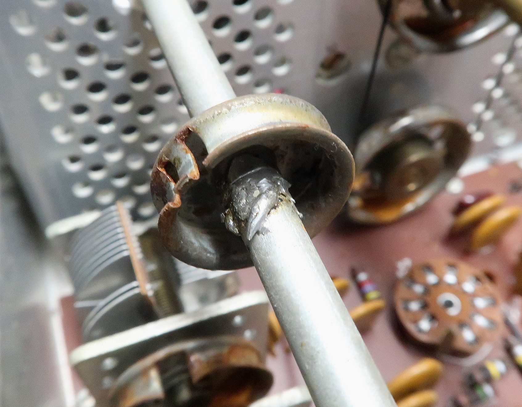
| Unrepaired Tuning Drum: In this picture the original soldering job can be seen. The drum is loose on the shaft, but still turns with the shaft due to the solder built up on the shaft. |
Preparation Before Gluing: A Dremel tool is used to grind off any solder and to free the drum, which is then slid down the shaft to expose the mounting area. The mounting area on the shaft is then cleaned with the Dremel tool so that the glue will properly adhere. (Be sure to cover the circuit boards around the drum with a paper towel to prevent any contamination during grinding.) |
Finished Repair: The shaft is coated with epoxy glue and the drum slid into position. A bead of glue is then applied to the drum as shown for extra security. |
Driver Preselector Belt
Replacement:
The Driver Preselector control shaft is connected to variable capacitors C421
and C422 via a pair of rubber drive belts. These belts stretch and wear with
time and are broken or stretched in many HW-101s. Mine were still unbroken, but
had stretched to the point that they no longer functioned. A variety of
replacements were found on e-bay. (Note that the SB-100, SB101, SB-102, HW-100,
and HW-101 all use the same belts.) A seller in South Korea offered red silicon
drive belts for a higher price, and I decided to go with those, since silicon
is more durable than rubber. The new belts were installed and work just fine,
as can be seen in the photo below.
Before installing the belts I carefully measured their sizes. Since they came
from South Korea, I assumed they would have metric dimensions. I
carefully measured them and found them to have an inner diameter of 50mm and
an outer diameter of 56mm.
 Click on the image for a super detailed view. |
| The rubber Driver Preselector belts were
replaced with silicon belts obtained on ebay. The new belts have an inner
diameter of 50mm and an outer diameter of 56mm. They are 3mm thick. |
Shunting of Resistor R202:
R202 was a 10k ohm 1/2W resistor that originally connected the output of the
first IF amplifier (V3) on the IF amplifier board to the grid of the first
transmit mixer (V5A) on the bandpass filter board. It was only present in early
run HW-101s, and was removed by Heathkit on later runs. My copy of the 1970
manual and the schematic diagram do not show the resistor, though it was
present in my HW-101, indicating that my unit was a very early HW-101.
Rather than remove the resistor and replace it with a wire, I shunted the
resistor with a piece of wire and left it in place. This effectively
removes the resistor from the circuit but also alerts a possible future
owner that the resistor was originally present, and that my unit was an
early run unit. See the picture below:
 Click on the image for a super detailed view. |
Chassis Cleaning:
My standard procedure when restoring gear is to first clean as much of the
chassis as possible with a very small rag or piece of paper towel and Fantastic
cleaner. Never spray the cleaner directly onto the work! Instead,
very lightly wet the paper towel/rag with the cleaner and wipe the
surface. You must be careful not to let excess liquid wick itself into
undesirable places! When finished, replace the Fantastic cleaner with water
and rinse the surface. Again, never spray the work directly.
In some special cases I will use Ronsonol lighter fluid (naptha). (Over the
years I have found that lighter fluid is relatively benign and does a great job
of cutting through certain grease and other deep grime.) If you are in doubt as
to whether to use the lighter fluid on a surface, test a small inconspicuous
area first.
After as much as possible is done with the rag/paper towel, I then switch to
using Q-tips to get into the tight places. Don't use any brand other than
Q-tips! (On cheaper brands the cotton isn't fastened well and often just
falls off.) I mount my Q-tips in a special knurled brass handle that I made to
hold them, as shown in the photo below:

Brass Holder For Q-tips.
Click on the image for a larger view.
The handle is made of 7/32" brass 6" long (aluminum would be fine
too). A 1/2" deep hole is drilled in one end with a #39 drill bit
(0.099") that provides a snug fit for the Q-tip. The Q-tips are cut off
with a pair of side cutting pliers and then inserted into the end of the
handle, as shown in the photo. The handle allows me to get into all of the
tight places on the chassis that cannot otherwise be reached. You can control
the flex of the Q-tip by how much of the shaft you leave on the Q-tip. I
usually cut my Q-tips in half, and do a whole bunch at once to save time.
To use the Q-tip, touch it to the outlet of the cleaner bottle and barely
pull the handle on the cleaner bottle. If you get it too wet, touch it to a
small rag or piece of paper towel to remove the excess. When the Q-tip gets
dirty, take it out and insert another. You will go through a lot of Q-tips, and
it is much like cleaning the floor of your kitchen with a toothbrush, but you
can get to all of those tight places and get them all clean.
I even clean the components (variable capacitors, especially the
steatite/ceramic insulation, fixed capacitors, resistors, and coils (after
carefully testing on a small part of the coil)) this way as well. Yep, the
process is time consuming, but it is about the only way to really get the
chassis clean.
After everything is cleaned, the entire process is repeated using Pledge
furniture polish to resist dust build-up and give everything a nice shine.
As before, don't directly spray the work. When using the Q-tips with the wax,
touch the Q-tip with the outlet of the Pledge bottle and barely press the
spray button. Some wax will wet the Q-tip and usually some excess will
remain on the can. You can mop the excess up wax up with other Q-tips. If you
get the Q-tip too wet, touch it to a small rag or piece of paper towel to
remove the excess.
Circuit Board Cleaning:
The circuit boards are cleaned in exactly the same way as the chassis, except
that only Q-tips are used. I clean the components as well as the circuit board
itself. Coil shields and IF transformers are cleaned along with everything
else. You must be very careful not to let excess fluid get anywhere, but
with a little practice you will find that this isn't a problem. With the Q-tips
you can get down between components and really get the dirt out. The photo
below shows what the circuit boards will look like after they have been cleaned
and waxed. The wax isn't just for looks. It helps to prevent dust from
adhering in the future, so that a simple vacuuming with a camel hair brush will
be enough to bring things right back.
It all takes a lot of time, but in the end it is worth it!
 Click on the image for a super detailed view. |
 Click on the image for a super detailed view. |
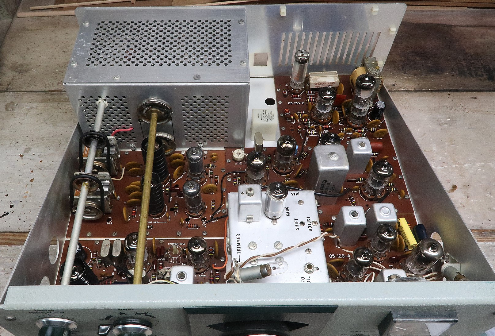
| Interior Before Cleaning Before cleaning the circuit boards and tubes are covered with dirt. The relay, IF cans, and chassis are covered with a yellow haze. The top of the high voltage cage is covered with a couple of large dirt patches. |
Interior After Cleaning After cleaning the circuit boards are clean and bright, and the tubes gleam in the light. The yellow haze on the relay, IF cans, and chassis is gone. The top of the high voltage cage shines without any dirt. |
High Voltage Cage Cleaning:
The high voltage cage is cleaned in the same manner as the chassis, but it is
much more difficult to clean within the confines of the cage. The cage is also
much dirtier than the rest of the chassis because the heat from the final tubes
causes more air to circulate, bringing in more dirt. The final tubes are
carefully removed and then Q-tips are used with Fantastic to scrub away the
dirt. With the Q-tip tool, the Q-tips can be bent into a gentle curve, allowing
one to clean under the coil and other areas otherwise inaccessible. With heavy
dirt, the Q-tip is wet with cleaner a little more than normal, and the dirt is
scrubbed into a slurry. Before the slurry dries, a fresh dry Q-tip is used to
"mop up" the slurry.
The coils, relay, fixed capacitors, parasitic suppressors, and variable
capacitors are also cleaned, but with these you must be careful not to
let any fluid wick its way into places it shouldn't be, such as the variable
capacitor bearings. A pipe cleaner is used to clean the space between the
plates of the upper tuning capacitor. You must be careful around the red RF
choke, as the wire is delicate, and you don't want to break it off at the
top.
After everything is cleaned, the entire process is repeated using Pledge
furniture polish to resist dust build-up and give everything a nice shine.
The picture below shows how the high voltage cage looks after it has been
cleaned and polished.
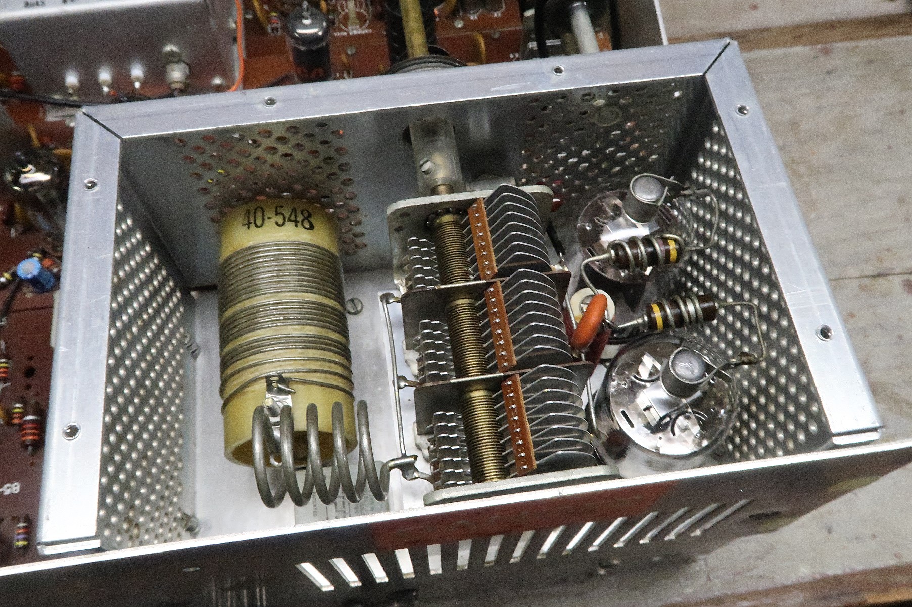 Click on the image for a super detailed view. |
Cabinet Cleaning and Waxing:
The cabinet was thoroughly scrubbed down with Soft Scrub cleaner. This is a
very fine abrasive cleaner and it was very effective in removing dirt that had
worked its way down into the finish. The cabinet was then flushed with hot
water and a sponge was used to remove any Soft Scrub that might have remained.
Finally, the cabinet was waxed with Pledge furniture polish. This brought back
the original shine and the cabinet looked brand new.
 Click on the image for a super detailed view. |
 Click on the image for a super detailed view. |
| Cabinet Before Cleaning The cabinet was initially filthy, as can be seen in this photo. Some areas had a black "grime" on them, others just looked very worn. |
Cabinet After Cleaning The cabinet shines as if brand new. |
Front Panel And Knob Cleaning:
At first I considered removing the front panel for cleaning but decided that it
would be easier to clean it in place.
The first step in cleaning the front panel was to carefully remove the knobs.
Next, the set screws were removed from the knobs, and the brass reducing
sleeves in the Final/Pate Tune and RF Gain controls were carefully removed. The
knobs were then scrubbed down with a toothbrush and SoftScrub. The toothbrush
dug into the nooks and crannies on the knobs and removed any dirt that was
there. The toothbrush also removed any patina that had built up on the knobs
over the years. After washing, compressed air was used to blow out any residual
water and the knobs were left to fully dry. The knobs were then waxed with
Pledge furniture polish, which brought back the original shine. Some of the
knobs had bent skirts. These were carefully straightened with pliers. The set
screws and bushings were then reinstalled.
After the knobs were cleaned, the retaining nuts and washers were removed from
all of the controls to expose as much of the panel as possible. The panel was
then broken down into five sections: upper left, lower left, upper right, lower
right, and center.
To clean a section of the panel, a rotary Oral B electric toothbrush and
Softscrub were used. A rotary electric toothbrush was used because of
the random structure of the wrinkled finish. Some SoftScrub was applied to the
toothbrush and then manually brushed onto a section of the panel without
power to the tooth brush. This prevented spattering of the SoftScrub. After
application, and after the toothbrush was in contact with the panel, the
toothbrush was turned on and the the panel section scrubbed down. Screws, the
headphone jack, and the mic jack were scrubbed as well, but no abrasive was
allowed into sensitive interior areas. To avoid spattering, the toothbrush
was never powered unless it was in contact with the panel. After a section
was scrubbed, it was carefully rinsed with a small sponge. Then the toothbrush
was used again with pure water only. This scrubbed out any residual
abrasive. The water was absorbed with a paper towel. This was continued until
all of the abrasive was removed. The sections were done in the order listed
above to provide some overlap.
When cleaning the center section, great care was used to avoid getting any
abrasive into or onto the frequency window or the front of the meter. To do
so would dull the plastic. Instead, Fantastic cleaner and Q-tips were used to
clean the front and back of the frequency window and meter. The front of the
round rotary frequency scale was also very carefully cleaned with Q-tips
and Fantastic cleaner.
After cleaning, the panel was waxed with Pledge furniture polish, and the
retaining washers, nuts, and knobs were reinstalled. The result was a front
panel that looked brand new, as can be seen in the pictures below:
 Click on the image for a super detailed view. |
| Front Panel Before Cleaning Before cleaning the front panel is filthy, with some kind of black "grime" everywhere. The slide switches, meter, and frequency scale are dirty. |
Front Panel After Cleaning After cleaning the front panel is clean and bright, and the knobs gleam in the light. The frequency scale and meter are easy to read and the the transceiver looks brand new. |
Replacement of the Crystal for the 29.5 MHz
Band:![]()
When I first got my HW-101 I found that the 29.5 MHz band was dead. All other
bands were fine. Connecting a frequency counter through a small capacitor to
pin 3 of V19B, the cathode of the heterodyne oscillator cathode follower,
showed that there was no output on the 29.5 MHz band. Since there was output in
all other positions of the band switch the problem had to be with the crystal,
with L608 ,with the adjustment of L608, or with the connections to them.
If you have a crystal that doesn't seem to be operating, don't replace it
with another until you have:
1. verified the connections to it and its associated coil via the bandswitch
2. tried readjusting the coil associated with it
One way to test the coil is to use a grid dip meter next to the coil to see if
it resonates at the crystal frequency. Note that the crystal frequency is
8.895 MHz higher than the frequency marked on the band switch. For example,
in this case, 29.5 MHz + 8.895 MHz = 38.395 MHz.
In my case, an ohmmeter verified that the connections to the crystal and L608
were OK. My grid dip meter confirmed that L608 did resonate around the crystal
frequency of 38.395 MHz. Adjustment of L608 through its entire range did not
fix the problem. The problem had to therefore be the crystal.
I was fortunate to have a spare HW-101 for parts. I used Solder-Wick and
carefully unsoldered the defective crystal from my HW-101 and the
"new" crystal from the spare HW-101. I then soldered the
"new" crystal into my HW-101. When soldering and unsoldering
crystals use as little heat as possible. Crystals can be ruined with too
much heat.
I had no way of knowing the condition of the "new" crystal until it
was soldered back into my HW-101. It did not initially work, but it came to
life after I readjusted L608. Problem solved!
Lacking a spare HW-101 for parts, it is possible to find replacement crystals
on the internet from ebay and other sources. Remember that the HW-101 and
SB-102 use the same crystals. This may improve your chances of finding a
replacement crystal.
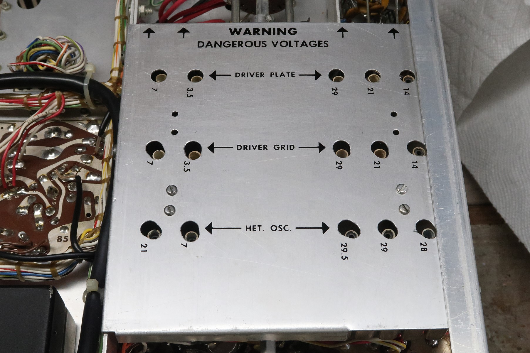
Coil Cover Modification:![]()
The cover on the driver plate, driver grid, and heterodyne oscillator coils
should be in place when these coils are adjusted. However, the driver grid and
heterodyne oscillator coils in my HW-101 were positioned such that when the
coil cover was in place they could not be adjusted. Rather than using a drill
to enlarge the holes, which would remove too much metal, I carefully used a
Dremel tool with a 1/8" high speed steel cylindrical bit (Dremel #194) to
enlarge the holes until the coils could be adjusted with the cover in place.
You can see the modified coil cover in the picture below.
 Click on the image for a super detailed view. |
| The coil cover after modification. Some
coils were originally completely covered and could not be adjusted with the
cover in place. |
 Back to Dr. Greg Latta's
Electrical Engineering and Amateur Radio Pages
Back to Dr. Greg Latta's
Electrical Engineering and Amateur Radio Pages
 If you have any questions or
comments, you can send E-Mail to Dr. Greg Latta at
glatta@frostburg.edu
If you have any questions or
comments, you can send E-Mail to Dr. Greg Latta at
glatta@frostburg.edu