
Important Safety Note: Working on or testing equipment such as the Heathkit HW-101 transceiver and the HP-23 power supply is extremely dangerous since very high voltages are present when the equipment is turned on, and may even be present when the equipment is turned off and unplugged. If at all possible, do all work with the equipment off and unpluggedand be sure that the capacitors are properly discharged before working on the equipment. The operator assumes all risk and liability in such matters! Do not work on this type of equipment unless you are experienced with working around very high voltages!
Introduction:
There are many "improvements" out there for the HW-101. Some,
however, are questionable and the advice here is "owner beware". Now
that some HW-101s may be 50 years old, they are antiques, and I seriously
question any modifications that were not done/recommended by Heathkit.
Modifications that involve physical alteration of the chassis should in
particular be avoided. For example, though it is very tempting to replace the
antenna connector (originally an RCA phono jack) with an SO-239 coaxial
connector (as was done on my HW-101), this should be avoided since it is very
easy to buy or make an adaptor and avoid physical modification of the
transceiver.
There are two modifications, however, that are recommended. Both of
these were recommended by Heathkit and incorporated into the manual. The first
is shunting/removing resistor R202. The second is
replacing resistors R106 and R107 in the S-meter
circuit with higher power resistors to reduce S-meter drift.
So why do I include information on other modifications here? Because some of
these may have been done on your HW-101 and the information may be of help
to you. Also, if your HW-101 is already modified, then you might consider some
additional modifications. It is up to you.
73 and see you on the air,
Greg AA8V
| Shunting of
Resistor R202: This is one of two modifications that should always be done, since it was recommended by Heathkit and incorporated into later HW-101s. R202 was a 10 kohm 1/2 W resistor that originally connected the output of the first IF amplifier (V3) on the IF amplifier board to the grid of the first transmit mixer (V5A) on the bandpass filter board. It was only present in early run HW-101s, and was removed by Heathkit on later runs. My copy of the 1970 manual and the schematic diagram do not show the resistor, though it was present in my HW-101, indicating that my unit was a very early HW-101. Rather than remove the resistor and replace it with a wire, I shunted the resistor with a piece of wire and left it in place. This effectively removes the resistor from the circuit but also alerts a possible future owner that the resistor was originally present, and that my unit was an early run unit. See the picture at right. |
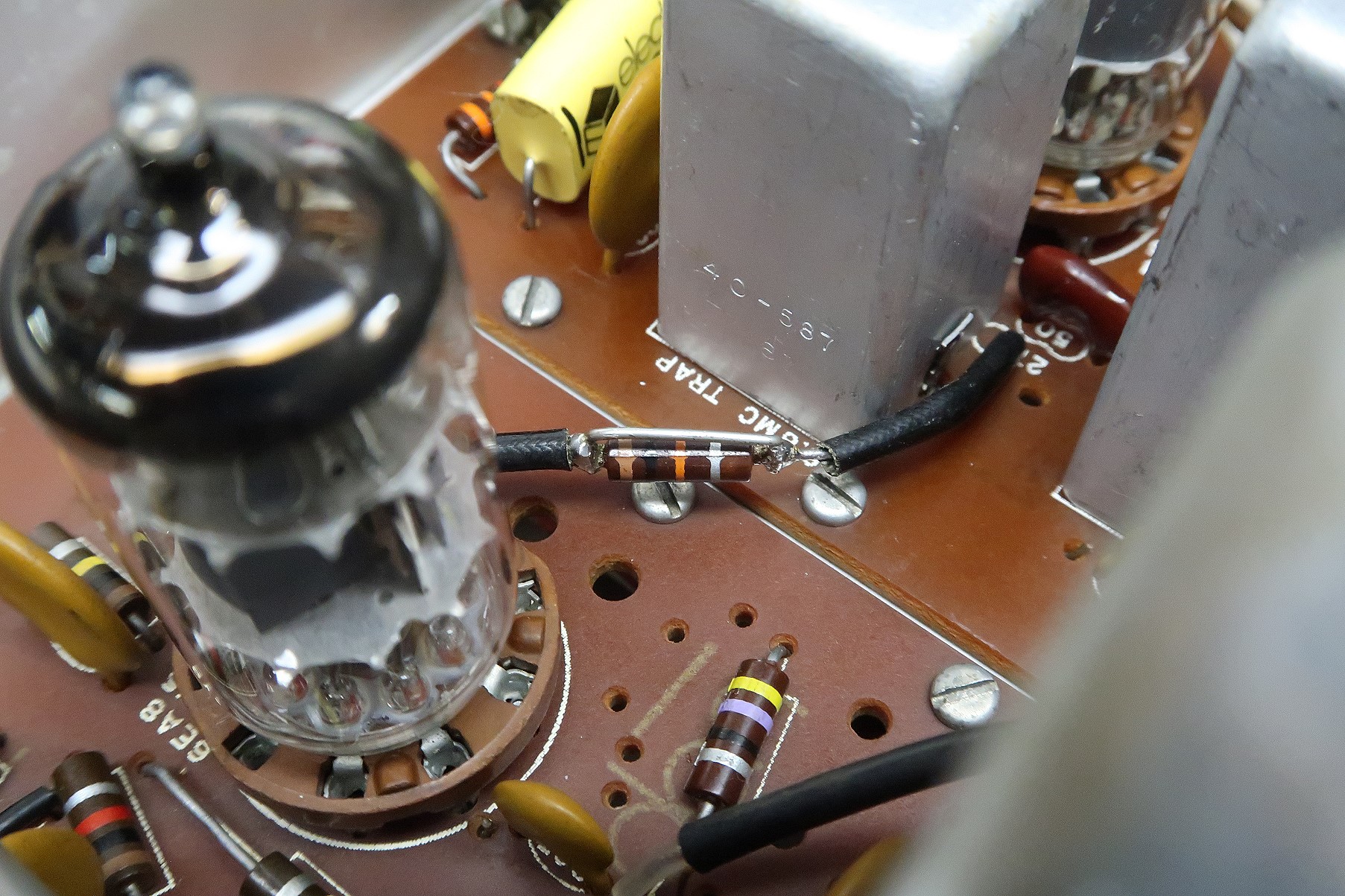 Click on the image for a super detailed view. |
| Replacing
Resistors R106 and R107: This is second of two modifications that should always be done. Resistors R106 and R107 form a voltage divider that is part of the S-Meter circuit. They tend to change value when they heat up and cause the S-Meter to drift. By replacing them with higher wattage units the S-Meter drift will be reduced. R106 is originally a 22 kohm 1 watt resistor. It should be replaced with a 2 watt resistor, preferably a wirewound unit. Be very careful when replacing this unit since there a four other connections to one of the circuit board pads to which R106 is connected. One of these is to another resistor and the other three are to the wiring harness. Be sure that all of these are still connected after R106 is replaced. R107 is a 100 kohm 1/2 watt resistor. It should be replaced with a 100 kohm 1 watt resistor. See the diagram at right for the location of the resistors. |
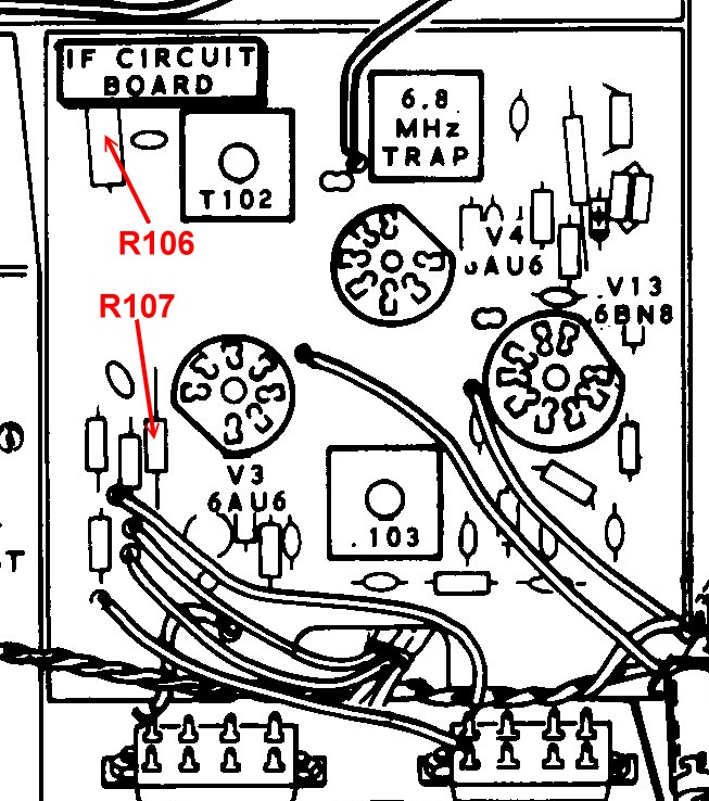 Click on the image for a super detailed view. |
| Optimizing the HW-101, SB100-102 Transceivers: A nine page article by Mark, WB8JKR, on modifications that can improve the HW-101 and SB100-102 transceivers. The modifications include the following: Conversion to Low-Z Headphones Improved CW Operation Transmit Improvements Receive Improvements I.F. Filter Passband Improvements Stabilizing Meter Zero Settings |
 Click here or on the image above for Optimizing the HW-101, SB100-102 transceivers. |
| Improving the Heathkit HW-101 Transceiver: A three page article covering: I.F. Screen Voltage Bandpass Filter Realignment Replacing V10 and V11 VFO Stability ALC/S-Meter Zero VFO Tuning Mechanism Erratic Transmit/Receive Action S-Meter Readings Birdies Pilot Lamps Stop S-Meter Drift Bad 6AU6 Tubes |
Click here or on the image above for an article on Improving the HW-101 transceiver. |
| Receiver Offset Tuning for the SB-101: These two pages are from the March 1969 issue of QST magazine. They explain how to add receiver offset tuning (now known as receiver incremental tuning or RIT) to the Heathkit SB-101 transceiver. Thought not specifically for the HW-101, the two transceivers are similar enough that you may find this useful in adding receiver offset tuning to the HW-101. |
 Click here for an image of March 1969 QST Page 46. |
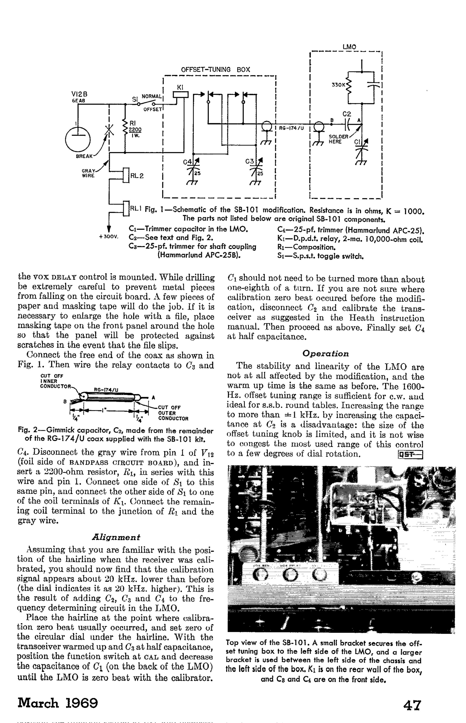 Click here for an image of March 1969 QST Page 47. |
 Back to Dr. Greg Latta's
Electrical Engineering and Amateur Radio Pages
Back to Dr. Greg Latta's
Electrical Engineering and Amateur Radio Pages
 If you have any questions or
comments, you can send E-Mail to Dr. Greg Latta at
glatta@frostburg.edu
If you have any questions or
comments, you can send E-Mail to Dr. Greg Latta at
glatta@frostburg.edu