Fully Restored Power Supply - March 27, 2022
Click on the image for a super detailed view.
| Heathkit HW-101 - Main Page Photos of the Restored Transceiver | Alignment |
| Photos of the Unrestored Transceiver | Modifications |
| Transceiver Restoration | Schematic Diagrams |
| HP-23/PS-23 Power Supply Restoration | Manuals, Advertisements, and Data Sheets |
| Power Supply Schematic Diagram and Circuit Descriptions |
Important Safety Note: Working on or testing equipment such as the Heathkit HW-101 and HP-23 is extremely dangerous since very high voltages are present when the equipment is turned on, and may even be present when the equipment is turned off and unplugged. If at all possible, do all work with the equipment off and unpluggedand be sure that the capacitors are properly discharged before working on the equipment. The operator assumes all risk and liability in such matters! Do not work on this type of equipment unless you are experienced with working around very high voltages!
Introduction:
When I acquired my HW-101, it also came with a power supply. The power supply,
however, was not made by Heathkit. Instead, it was a homebrew
(homebuilt) unit. Close inspection revealed that the circuit was identical to
that of the Heathkit HP-23 series, and, more importantly, that the power
transformer was made by Heathkit and had the same part number as the
transformer used in the Heathkit PS-23/HP-23C. For all intents and purposes,
the unit was identical to the Heathkit PS-23/HP-23C.
Initial Cleaning:
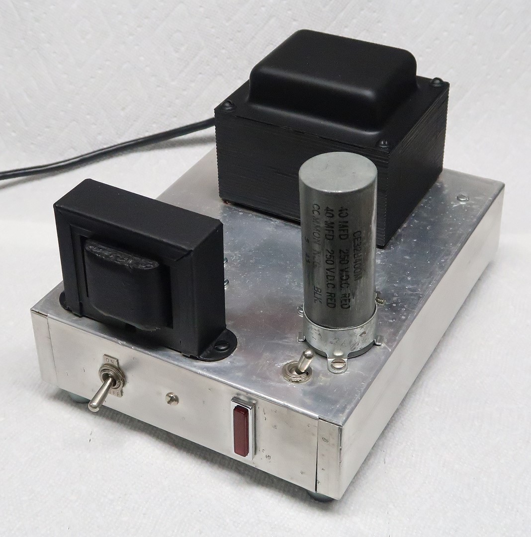
As received the power supply was in pretty decent shape. It was built on an
aluminum chassis that was spot welded in certain places and quite sturdy. The
wiring was sound, and nicely done for a homebrew unit. The power supply was
dirty, but not as bad as some old gear that I have encountered.
I wiped down the chassis , transformer, and choke with a slightly damp rag and
then rubbed out the aluminum chassis with Soft Scrub, a product used to clean
fine porcelain kitchen sinks without scratching them. This removed the dirty
patina from the aluminum. I then waxed the aluminum chassis with Pledge
furniture polish. Since I was planning on airbrushing the transformer and
choke, I was very careful not to get any of the polish on the transformer or
choke, which would prevent the paint from sticking.
Testing The Power Transformer:
The power transformer is one part in a power supply that is not easy to
replace. If the transformer is defective, then there is not much point in
restoring the power supply, so testing the transformer was the first order of
business.
The worst thing one can do is to plug in the power supply and turn it on,
hoping for the best. This is a sure road to disaster. The transformer, filter
capacitors, or diodes could be defective, leading to at best a blown fuse and
at worst a fire. First, an ohmmeter should be used to make a thorough check of
the primary circuit (AC plug, fuse and holder, On/Off switch) to check for
shorts and other problems before the power supply is even plugged in.
The power supply primary circuit checked out OK, so the red, blue, and
brown-yellow transformer leads were be disconnected. This removes any possible
load from the transformer secondaries. Next, a shorting wire was connected
between pins 9 and 10 of the 11 pin socket to simulate a closed On/Off switch
on the transceiver.
The power supply was plugged into a VARIAC (variable AC source)
and a voltmeter was placed across the high voltage secondary. The VARIAC was
set for 10% (about 12V), and the power supply was was turned on. The voltage on
the high voltage secondary was observed to be 10% of the expected value. The
other secondaries were also checked, and all showed 10% of the expected value.
The VARIAC was slowly increased to 25%, 50%, 75% and finally 100% with checks
on the secondary voltages each time to confirm proper operation. No other
problems were observed. The transformer appeared to be OK.
Testing The High Voltage, B+ and Bias
Circuits
Once the transformer checked out, the transformer leads were left
unconnected and the other circuits were tested with an ohmmeter and a
capacitor tester. A schematic diagram is
available at the bottom of this page, and a
complete circuit
description is also available as a separate web page.
All of the diodes tested OK, but it was quickly found that three of the
electrolytic capacitors were defective. One of the large 100uF/450V capacitors
in the high voltage section (C1) had low capacity and both of the capacitors in
the bias section (C6 and C7) were open. Since C1 was bad, it was likely that
the other three capacitors C2, C3, and C4 would eventually go bad as well. In
addition to the bad capacitors, the 100k/2W resistors across C1 and C2 (R1-R4)
all measured 150kohm rather than 100kohm and would have to be replaced as well.
With so many bad parts, it was decided to gut the power supply and replace
ALL of the parts, including the diodes.
Ordering Replacement
Parts:
Mouser Electronics has been my preferred source source for electronic parts for
a long time. I spent an afternoon on the computer ordering the parts that I
would need to rebuild the power supply. In addition to the resistors,
capacitors, and diodes, a new 18-3 grounded line cord was also ordered, since
the one on the power supply was an old, ungrounded type.
Below is the list of parts that I ordered. At the time of writing (March 2022)
the links shown are valid, though they may obviously change with time, and
parts specifications may also change. The total cost (including taxes and
shipping) as of March of 2022 was less than $60.
| Description | Link | Source |
| High Voltage and B+ Capacitors C1, C2, C3, C4: | ||
| 150uF 500V Electrolytic Capacitor - 4 Required (Replace 125uF with 150uF) |
80-ESG157M500AQ5AA | Mouser Electronics |
| Low B+ Electrolytic Capacitor C5: | ||
| 47uf 450V Electrolytic Capacitor - 1 Required (Replace 40uF with 47uF) |
647-UPT2W470MHD | Mouser Electronics |
| Bias Supply Electrolytic Capacitors C6 and C7: | ||
| 47uF 160V Electrolytic Capacitor - 2 Required (Replace 40uF 150V with 47uF 160V) |
647-UPM2C470MHD | Mouser Electronics |
| Metal Film Bias Bleeder Resistor R8: | ||
| R8 27k 2W Metal Film Resistor - 1 Required Replace 1W with 2W) |
71-CCF02-J-27K | Mouser Electronics |
| Metal Film Bleeder Resistors R1-R5: | ||
| R1-R5 100k 2W Metal Film Resistor - 5 Required | 71-CCF02100KJKE36 | Mouser Electronics |
| Bias Resistor R7: | ||
| R7 1k 2W Metal Film Resistor - 1 Required | 71-CCF2-J-1K | Mouser Electronics |
| Line Cord : | ||
| 18-3 Line Cord - 2m (6 ft 7 in) 10A | 562-311007-01 | Mouser Electronics |
| Silicon Diodes D1-D7: | ||
| 1N4007 1000V PIV 1A Diode - 7 Required (Replace older 1N2071 with modern 1N4007) |
621-1N4007 | Mouser Electronics |
Some General Comments On Replacing
Electrolytic Capacitors:
Electrolytic capacitors contain an electrolyte that can dry out over the years.
They can still test and function fine if they contain only a fraction of the
electrolyte. When a vintage radio is first brought back on line the
electrolytic capacitors may function fine at first. However, after some use the
heat from the equipment may dry out what is left of the electrolyte and then
they fail.
In the long run, it is best to eventually replace all of the
electrolytic capacitors (called "recapping") in a piece of vintage
equipment. The needed capacitors can all be purchased and installed at the same
time. This saves shipping costs and avoids having to open up the equipment
multiple times.
When searching for electrolytic capacitors, you will find many more with
"radial" leads than with "axial" leads, and the radial
leaded capacitors are usually less expensive. Radial leads both come out of the
same end of the capacitor, and are perfect for circuit board mounting..
Axial leads come out on the opposite ends of the capacitor, like the
original capacitors in this power supply. However, they can easily be replaced
with radial leaded capacitors, as was done in this power supply.
To obtain a high enough voltage rating power supply capacitors may have to be
replaced with multiple identical units in series with appropriate equalizing
resistors across each. For power supply capacitors a higher capacitance and/or
voltage rating is OK. For electrolytic capacitors in speech amplifiers and
audio circuits the capacitance should not be changed, since this could
alter the frequency response. However, a higher voltage rating is OK.
"Can" capacitors and other units containing several capacitors are
very hard to find (or are very expensive) and can be replaced with individual
units. However, for can capacitors, disconnect the bad unit but leave
it in place for aesthetic purposes, as was done in this power supply.
New Parts Installation:
The original parts were mounted on terminal strips, and I used the same
mounting method when installing the new parts. I had to change things around
since the new capacitors had radial leads rather than axial leads and were much
smaller than the original capacitors. I have a big collection of terminal
strips and was able to come up with an efficient arrangement. This required
carefully drilling several new holes in the chassis to mount the new terminal
strips.
For the new power cord I already had a strain relief, but it required a hole
larger than 1/2" with two sides that were partly flat. After drilling the
old hole out to 1/2", I used the 1/2" drill bit diagonally and
carefully routed out the hole, using a file to make the flat sides, until the
strain relief fit properly.
The left picture below shows the original parts and wiring. The right picture
shows the new parts and wiring.
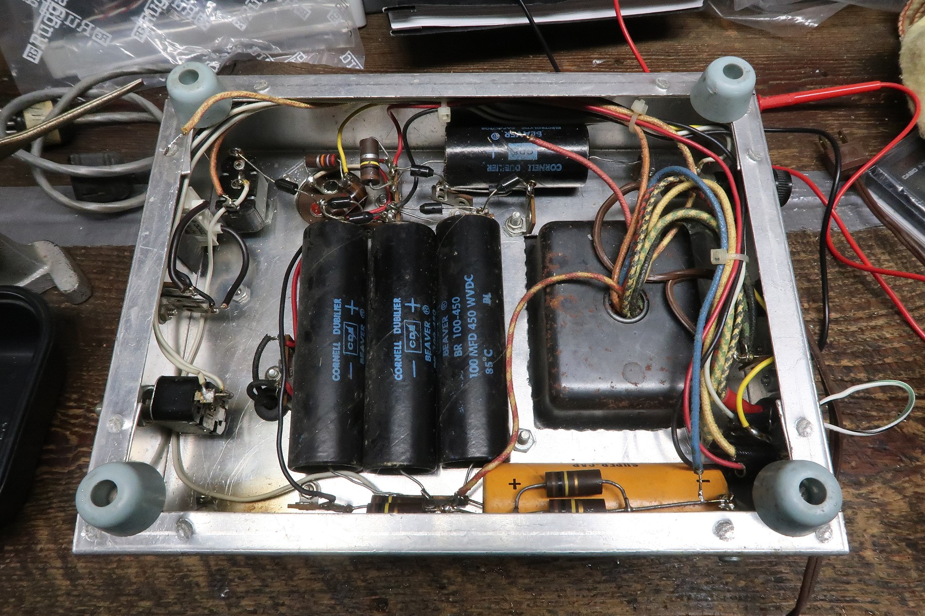 Before Rebuild Click on the image for a super detailed view. |
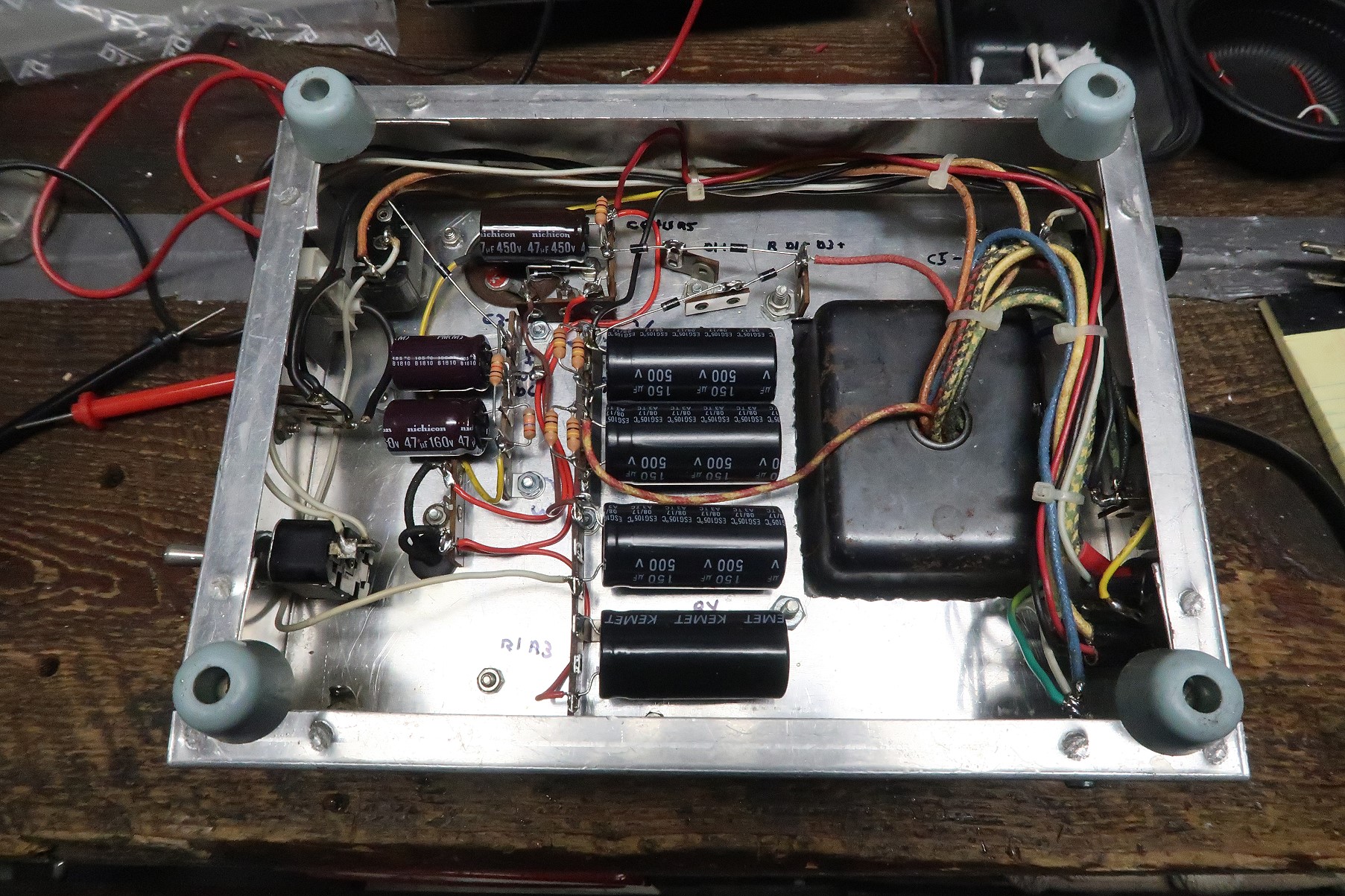 After Rebuild Click on the image for a super detailed view. |
I suggest you right click on the picture at right and open the enlarged
view in a separate window as you read the descriptions below:
Bias Supply Components:
At left center is a vertical 4-terminal strip with two purple electrolytic
capacitors that carries the bias supply components. The purple capacitors are
C6 (47uF/160V) and C7 (47uF/160V). Resistors R7 (1kohm) and R8 (27kohm) are
also mounted on this terminal strip. Diode D7 (1N4007) runs from the voltage
select switch at top left to the top of this terminal strip.
B+ Circuit Components:
B+ circuit components are mounted on a 6-terminal strip (bottom center), two
3-terminal strips (top center), and a 2-terminal strip at left bottom. The
bottom vertical 6-terminal strip holds C4 (150uF/500V, bottom) and C3
(150uF/500V, 2nd from bottom). At top, mounted on a vertical 3-terminal strip
is purple capacitor C5 (47uf/450V). Resistor R5 (100kohm) is also mounted on
this terminal strip. Immediately below C5 at top is a horizontal 3-terminal
strip that carries diodes D5 (1N4007) and D6 (1N4007). At bottom left a
vertical 2-terminal strip holds the black leads from the filter choke.
High Voltage Components:
Diodes D1-D4 (1N4007) can be seen at top center mounted on several small
terminal strips. Capacitors C1 (150uF/500V, top) and C2 (150uF/500V, 2nd from
top) can be seen mounted on a vertical 6-terminal strip at center. Bleeder
resistors R1-R4 (100kohm) are also mounted on this terminal strip.
Airbrushing:
Though the power supply was in pretty good shape, the transformer and choke
were rusted and I decided to airbrush them. This restores them to
better-than-new appearance, as can be seen in the pictures below. I used
Rustoleum Rusty Metal Primer (V7569502) and Rustoleum Flat Black (7578502). For
a video on airbrushing electronic equipment, visit my channel on YouTube,
"Greg Latta".
 First the choke and transformer are cleaned and the chassis is masked off. Click on the image for a super detailed view. |
 Next, the choke and transformer are given two coats of rusty metal primer. Click on the image for a super detailed view. |
 After the primer dries, two coats of flat black paint are applied. Click on the image for a super detailed view. |
 After airbrushing the power supply looks brand new! Click on the image for a super detailed view. |
Extending The Cable To The
Transceiver:
The output cable of my power supply was very short. The power supply had to be
kept relatively close to the transceiver. I wanted to place the power supply on
the floor, out of the way, so I decided to extend my cable by 3 feet.
New cable was impossible to find, so I made my own out of individual wires held
together with cable ties. When using this method, several rules must be adhered
to:
a. The wire for the high voltage line connected to pin 4 must be rated at
800V. The best wire for this purpose is test prod wire, which is rated at
1000V. (In my cable the original wire was not rated at 800V, but when
covered by the outer insulation it was adequately insulted.)
b. The wires connected to pins 2 and 6 should be #16 wire. These wires carry
the 5.5A filament current. Smaller wire could introduce a voltage drop,
lowering the filament voltage in the transceiver. Larger wire may cause
problems with the wire fitting into the pins on the connector.
c. #22 or larger wire is fine for all of the other wires.
1. The first step is to unsolder the wires from the female end of the cord that
plugs into the transceiver. After removing the cap I mounted the end in a vise
so I could pull on each wire with a pair of needle nose pliers while heating
the pin. Next, each pin is reheated while slapping the end down on the table to
knock out any remaining solder.
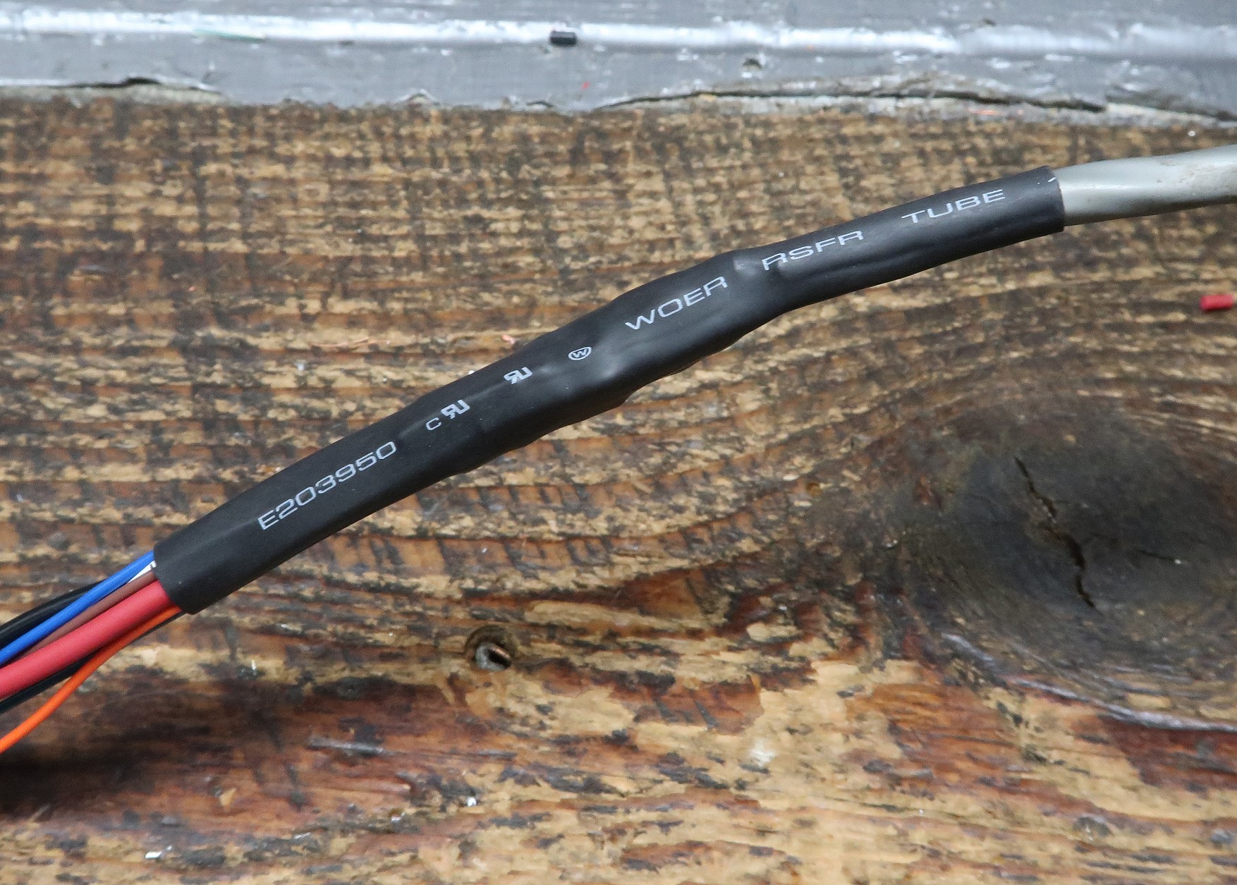
2. The new wires are soldered onto the old and each joint is covered with a
piece of heat shrink tubing. See the first picture below.
3. All of the splices are then covered with a single large piece of heat shrink
tubing. See the middle picture below.
4. The new wires are trimmed to the same length and soldered to the transceiver
connector. Don't forget to put the connector cap over the wires before
soldering the wires.
5. Cable ties are securely placed very three inches along the new wires. See
the picture at right below.
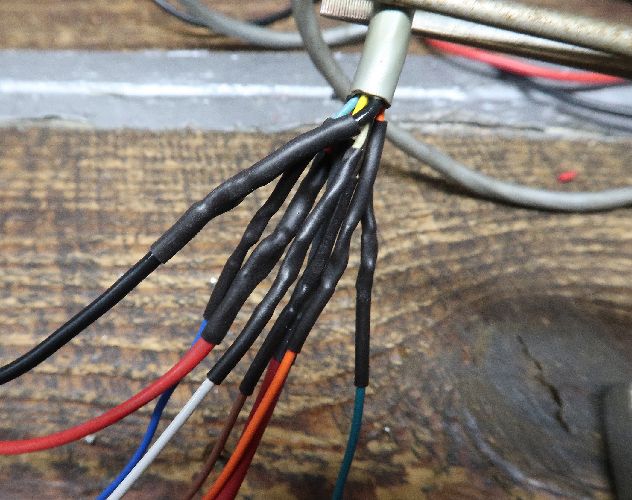 New wires are soldered onto the old and covered with heat shrink tubing. Click on the image for a super detailed view. |
 All of the wires are then covered with a piece of large heat shrink tubing. Click on the image for a super detailed view. |
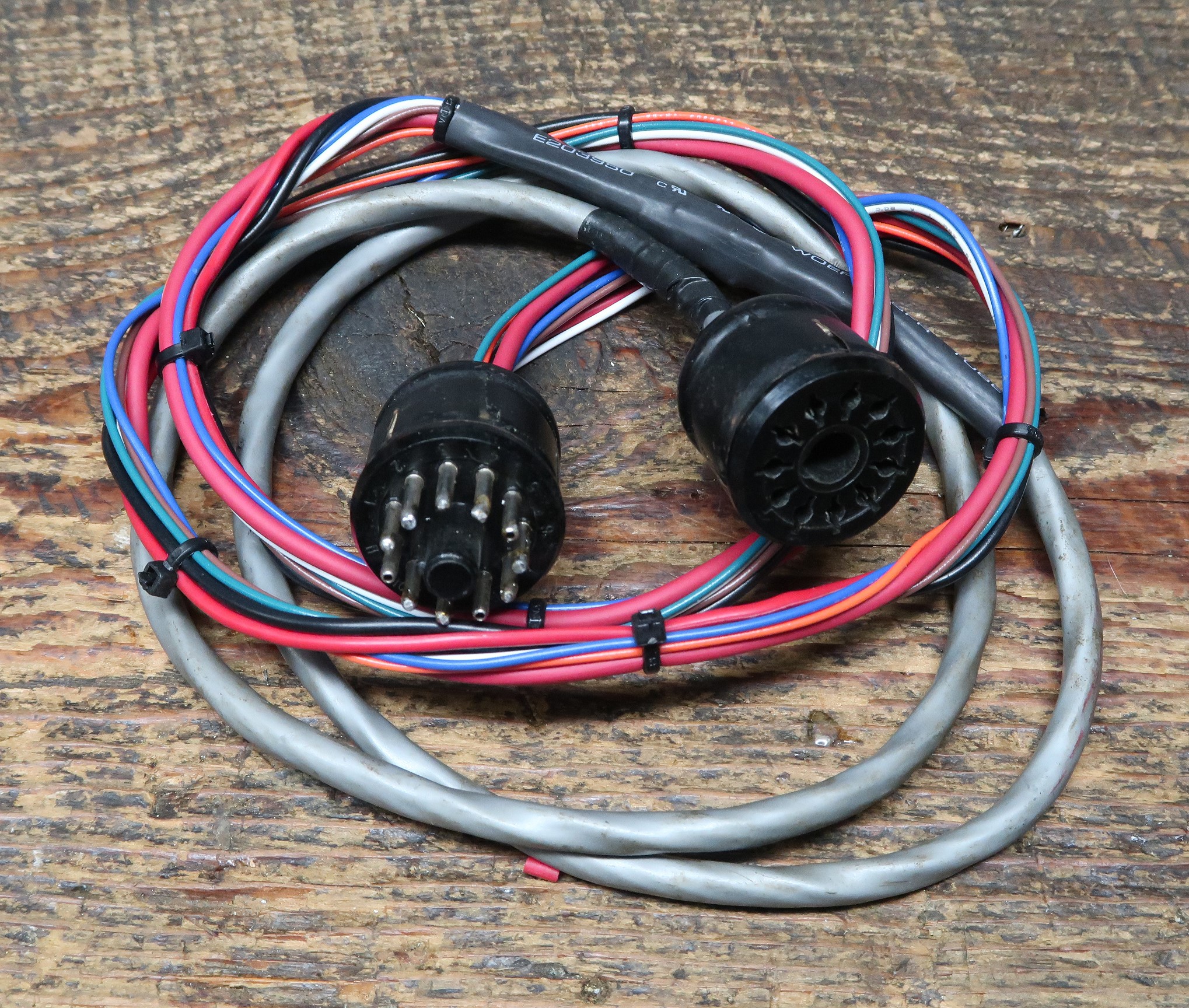 The Finished Cord Click on the image for a super detailed view. |
Schematic
Diagram:
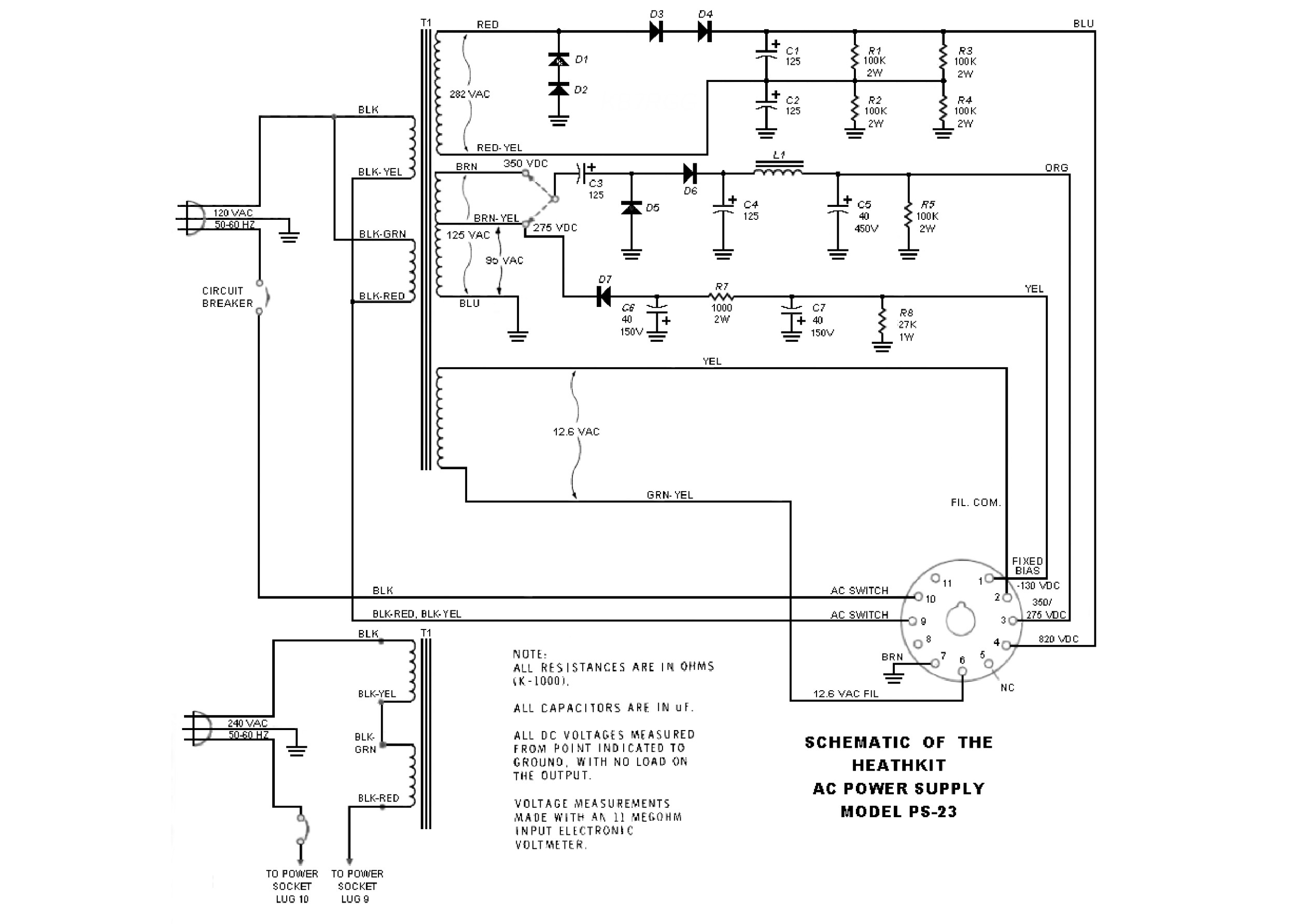
Below is the schematic diagram for the PS-23. It is the same as the diagram for
the HP-23C. The circuit diagrams for the HP-23, HP-23A, and HP-23B power
supplies are all very similar. Some have an On-Off switch, some have a 6.3V AC
filament tap, some have adjustable bias, etc. but they are all essentially the
same. For a detailed circuit description, go to the
Power Supply Schematic
Diagram and Circuit Descriptions page.
 Back to Dr. Greg Latta's
Electrical Engineering and Amateur Radio Pages
Back to Dr. Greg Latta's
Electrical Engineering and Amateur Radio Pages
 If you have any questions or
comments, you can send E-Mail to Dr. Greg Latta at
glatta@frostburg.edu
If you have any questions or
comments, you can send E-Mail to Dr. Greg Latta at
glatta@frostburg.edu