Click here or on the image for more pictures of the restored transceiver.
| Heathkit HW-101 - Main Page and Photos of the Restored Transceiver | Alignment |
| Photos of the Unrestored Transceiver | Modifications |
| Transceiver Restoration | Schematic Diagrams |
| Power Supply Restoration | Manuals, Advertisements, and Data Sheets |
| Power Supply Schematic Diagram and Circuit Descriptions |
Important Safety Note: Working on or testing equipment such as the HW-101 is extremely dangerous since very high voltages are present when the equipment is turned on, and may even be present when the equipment is turned off and unplugged. If at all possible, do all work with the equipment off and unplugged and be sure that the capacitors are properly discharged before working on the equipment. The operator assumes all risk and liability in such matters! Do not work on this type of equipment unless you are experienced with working around very high voltages!
About The Heathkit HW-101:
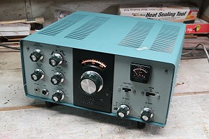
The Heathkit HW-101 was one of the most ubiquitous transceivers ever made. It
was sold from 1970 to 1983. The circuitry is nearly identical to the Heathkit
SB-102, but at a substantial savings. Some 30,000 to 40,000 were reported sold,
most assembled by hams at home. The transceiver operates on 80m, 40m, 20m, 15m,
and all of 10m (without the need for extra crystals). It features a pair of
6146 finals run in class AB1 which provide an input of 180W PEP on SSB and 170W
on CW. Output is 100W PEP on SSB and CW except on 10m, where it is 80W. The
receiver is double conversion with separate crystal filters for SSB and CW
(optional). The optional 400Hz CW filter can be switched from the front panel.
A separately available power supply (HP-23 or HP-13) is needed to run the
HW-101.
The tube lineup is as follows:
0A2 voltage regulator
6HS6 RF amplifier
6HS6 first receive mixer
6AU6 isolation amplifier
6AU6 1st IF amplifier
6AU6 2nd IF amplifier
6BN8 product detector and AVC
6AU6 VFO amplifier
6CB6 2nd transmitter mixer
6CL6 driver
6EA8 speech amplifier and cathode follower
6EA8 1st transmitter mixer
6EA8 2nd receive mixer and relay amplifier
6EA8 CW side-tone oscillator and amplifier
6GW8 audio amplifier and audio output
12AT7 heterodyne oscillator and cathode follower
12AT7 VOX amplifier and calibrator oscillator
12AU7 sideband oscillator
6146 final amplifier (2)
The diode lineup is as follows:
6 germanium diodes: balanced modulator, RF sampling, and crystal calibrator
harmonic generator
9 silicon diodes: ALC rectifiers, anti-trip rectifiers, and DC blocking
1 zener diode: cathode bias
The transistor lineup is as follows:
MPF-105 FET-VFO
2N3393 voltage regulator
| Front View |
| Top View |
| Side View |
| Bottom View |
| RF/Driver Board |
| Bandpass Board |
| IF Board |
| VFO |
| Carrier Oscillator Board |
| Audio Board |
| High Voltage Cage |
| Front View  Click on the image for a super detailed view. |
Top View 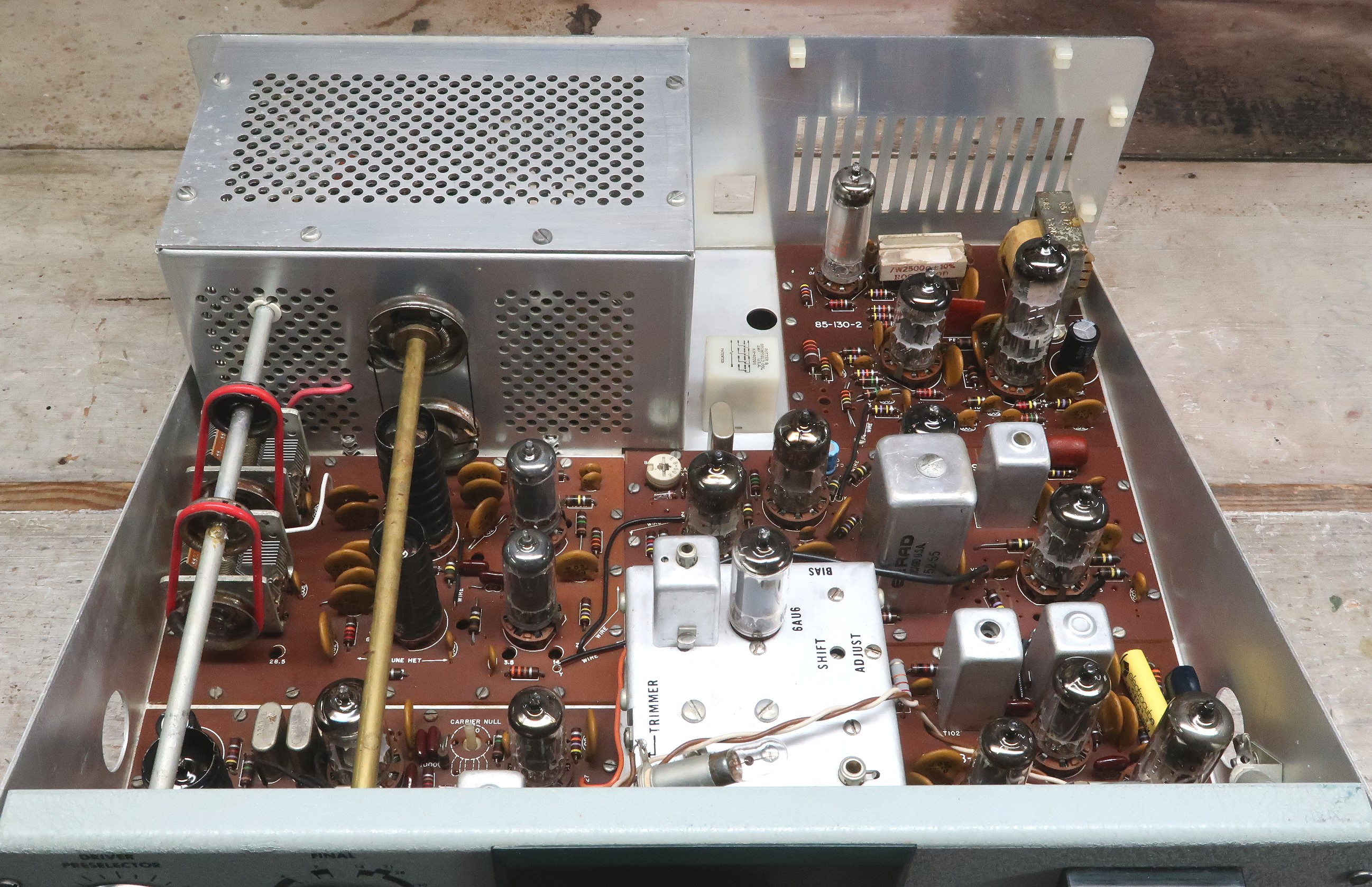 Click on the image for a super detailed view. |
| Side View  Click on the image for a super detailed view. |
Bottom View  Click on the image for a super detailed view. |
| RF/Driver Board  Click on the image for a super detailed view. |
Bandpass Board 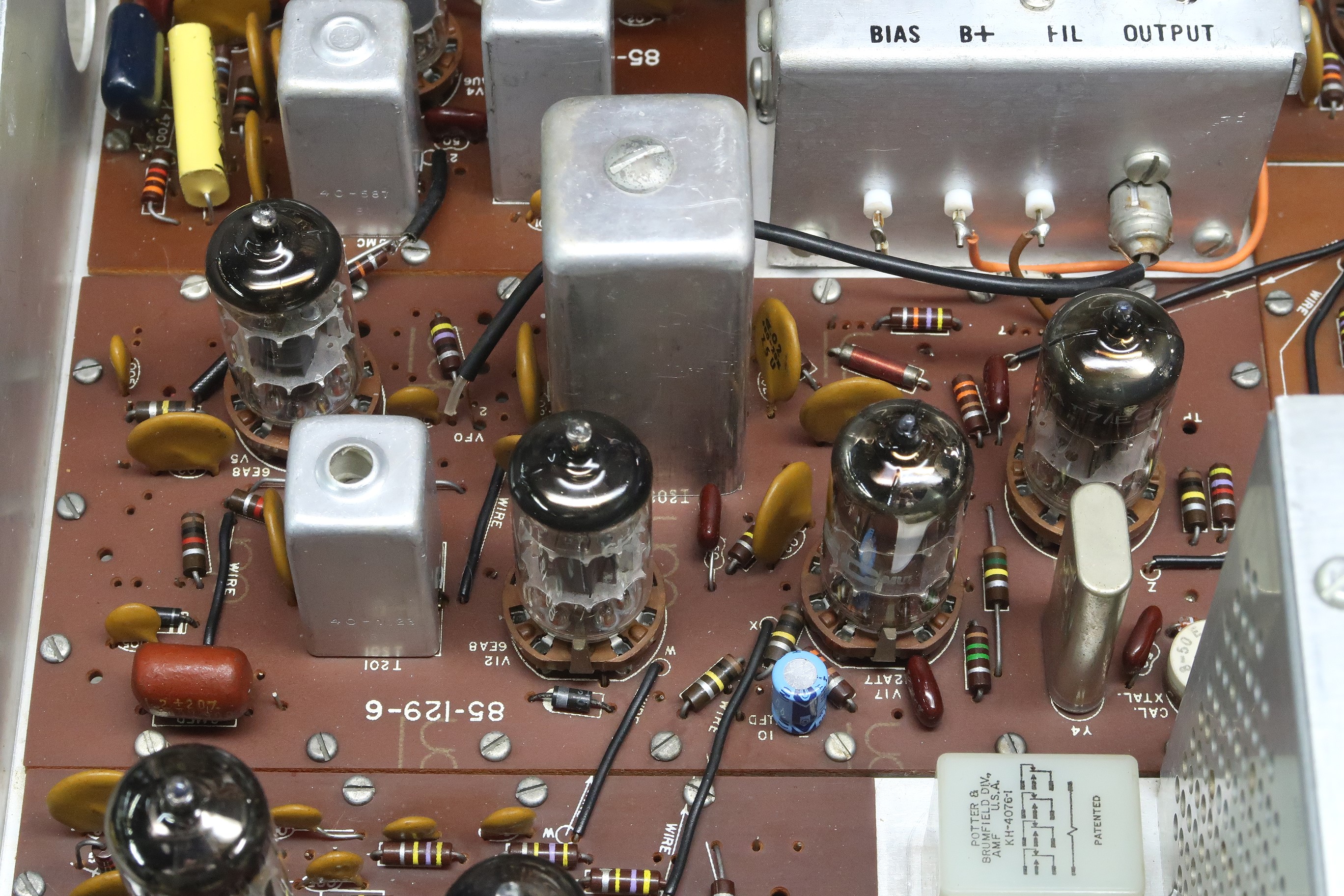 Click on the image for a super detailed view. |
| IF Board  Click on the image for a super detailed view. |
VFO 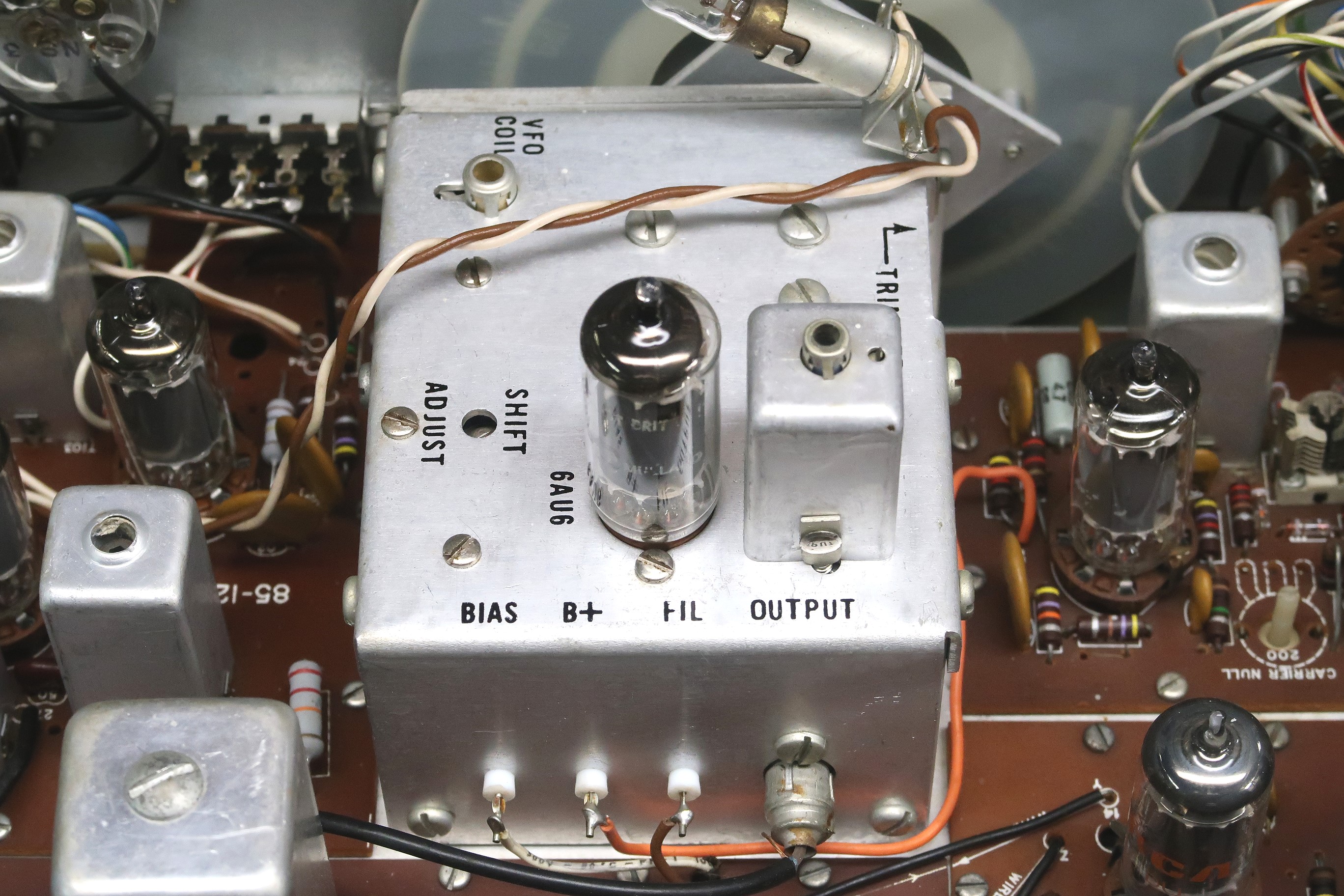 Click on the image for a super detailed view. |
| Carrier Oscillator Board  Click on the image for a super detailed view. |
Audio Board 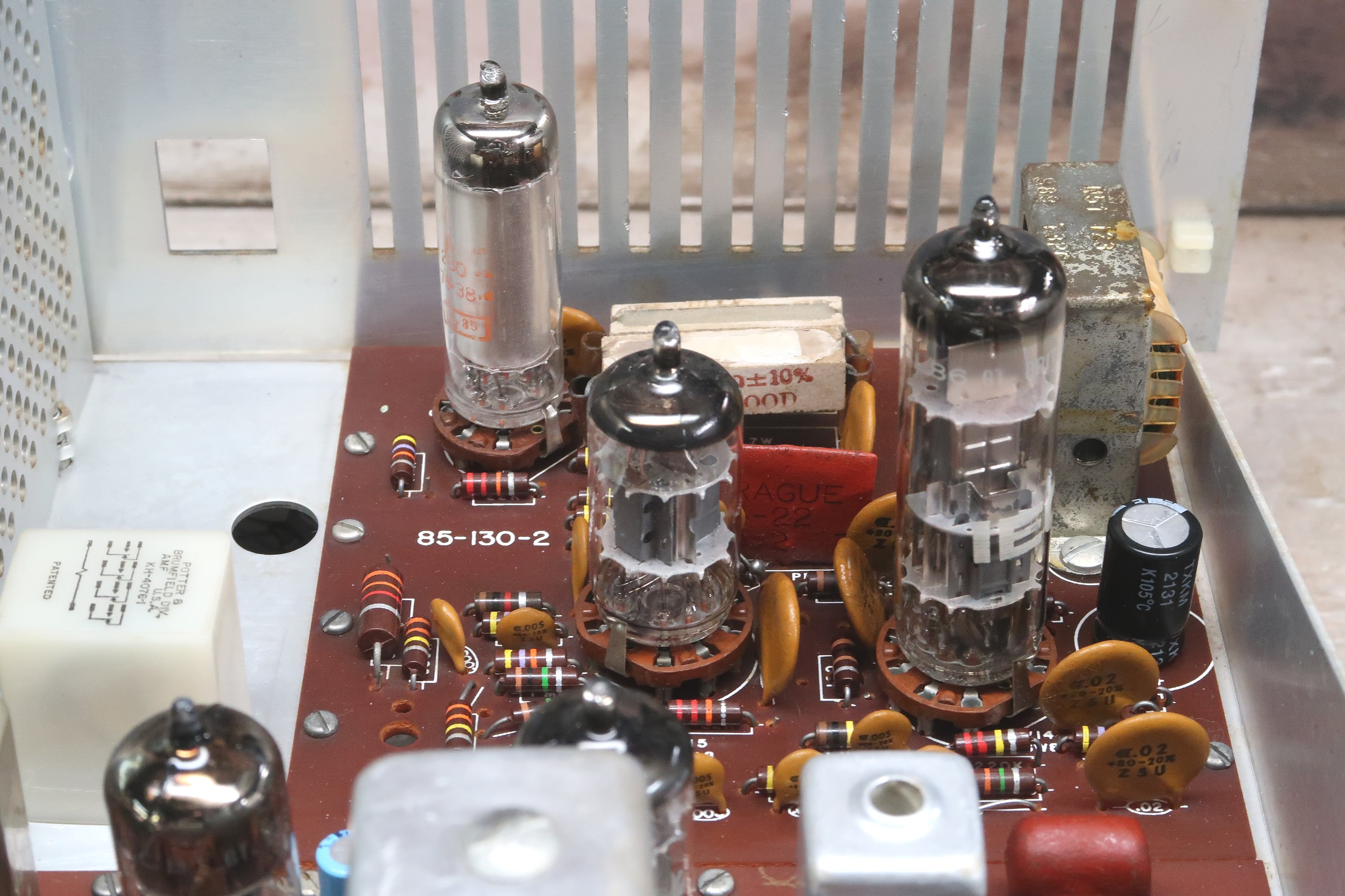 Click on the image for a super detailed view. |
| High Voltage Cage  Click on the image for a super detailed view. |
 Back to Dr.
Greg Latta's Electrical Engineering and Amateur Radio Pages
Back to Dr.
Greg Latta's Electrical Engineering and Amateur Radio Pages
 If you have any questions or
comments, you can send E-Mail to Dr. Greg Latta at
glatta@frostburg.edu
If you have any questions or
comments, you can send E-Mail to Dr. Greg Latta at
glatta@frostburg.edu