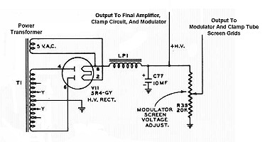
Click here for a higher resolution (larger) schematic.

Introduction:
The high B+ supply powers the
final amplifier,
modulator, and
clamper circuits. All of the other
circuits are powered by the low
B+ supply.
A 5R4-GY rectifier tube is used in a full wave center tapped configuration with
a choke input filter. The choke input filter allows the rectifier tube to
handle substantially more current than when used with a capacitor input filter.
As used in this circuit the 5R4-GY can handle a maximum current of about 250mA.
Nominal output of the high B+ supply is 500V.
High B+ Power
Supply
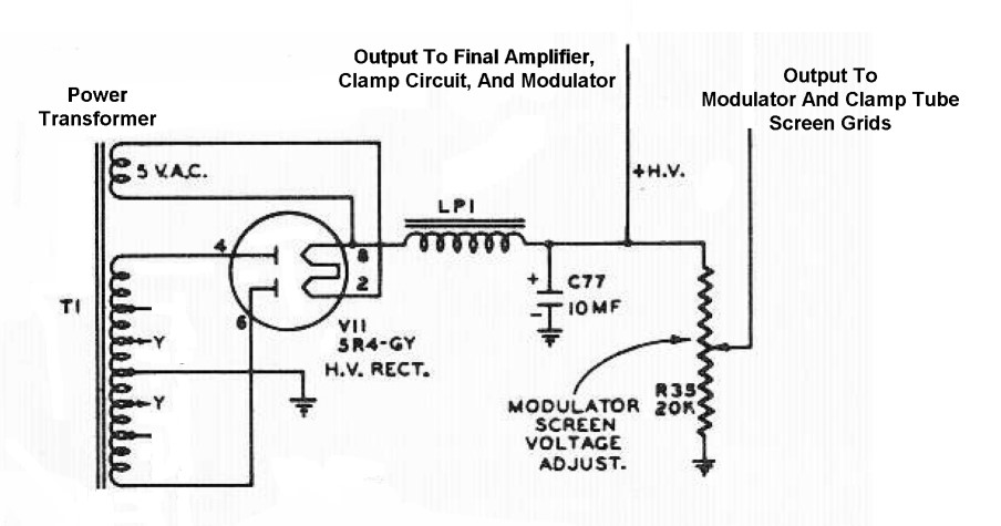
Click On A Section of the Schematic
Below for Information on That Part of the Circuit:
| 5R4-GY Rectifier Tube |
| Power Transformer T1 High Voltage Secondary |
| Power Transformer T1 Filament Secondary |
| Filter Choke |
| Filter Capacitor |
| Voltage Divider/Bleeder Resistor |
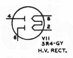
| 5R4-GY Rectifier Tube: The high B+ supply must provide a large amount of current. The 5R4-GY can handle up to 250mA when used with a choke input filter. The tube has a directly heated cathode, which means that a separate filament winding on the power transformer must be used, since the cathode is not at ground potential. You can click here for a 5R4-GY data sheet. |
 |
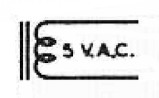
| Power Transformer T1 Filament Secondary: Power transformer T1 also supplies the filament power to all of the tubes in the Ranger. One 5V filament secondary winding powers the 5R4-GY high B+ rectifier, and another 6.3V secondary winding powers the rest of the tubes in the Ranger. |
|
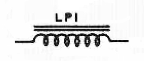
| Filter Choke: Filter choke LP1 blocks the AC component in the output of the 5R4-GY rectifier tube and passes relatively smooth DC to the filter capacitor, C77. A choke input filter lowers the peak current the rectifier tube must handle, and increases the overall average current that the rectifier tube can deliver. |
 |
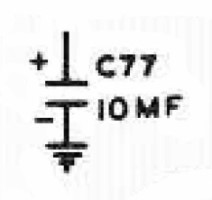
| Filter Capacitor: The relatively smooth output of the filter choke is additionally filtered by capacitor C77. The capacitor further smooths out the variations in the output of the filter choke to produce pure DC. |
 |
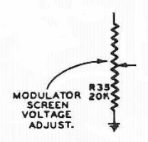
| Voltage Divider/Bleeder Resistor: R35, an adjustable 50W power resistor, is connected across filter capacitor C77 to improve the regulation of the high B+ supply and to provide the proper voltage to the modulator and clamper tube screen grids. R35 must be adjusted under the proper conditions to provide the correct voltage to the modulator screen grids. You can click here to find out how to properly adjust R35. |
 |
 Back to Dr.
Greg Latta's Electrical Engineering and Amateur Radio Pages
 If you have any questions or
comments, you can send E-Mail to Dr. Greg Latta at
glatta@frostburg.edu