
| Main Page and Exterior Photos | How To Use A Regenerative Receiver |
| Interior Photos of the Receiver | Receiver Schematic Diagram and Circuit Description |
| L1 and L2 Coil Specifications | 6SN7 Dual Triode |
| Twinplex Receivers Built By Others | Modifications |
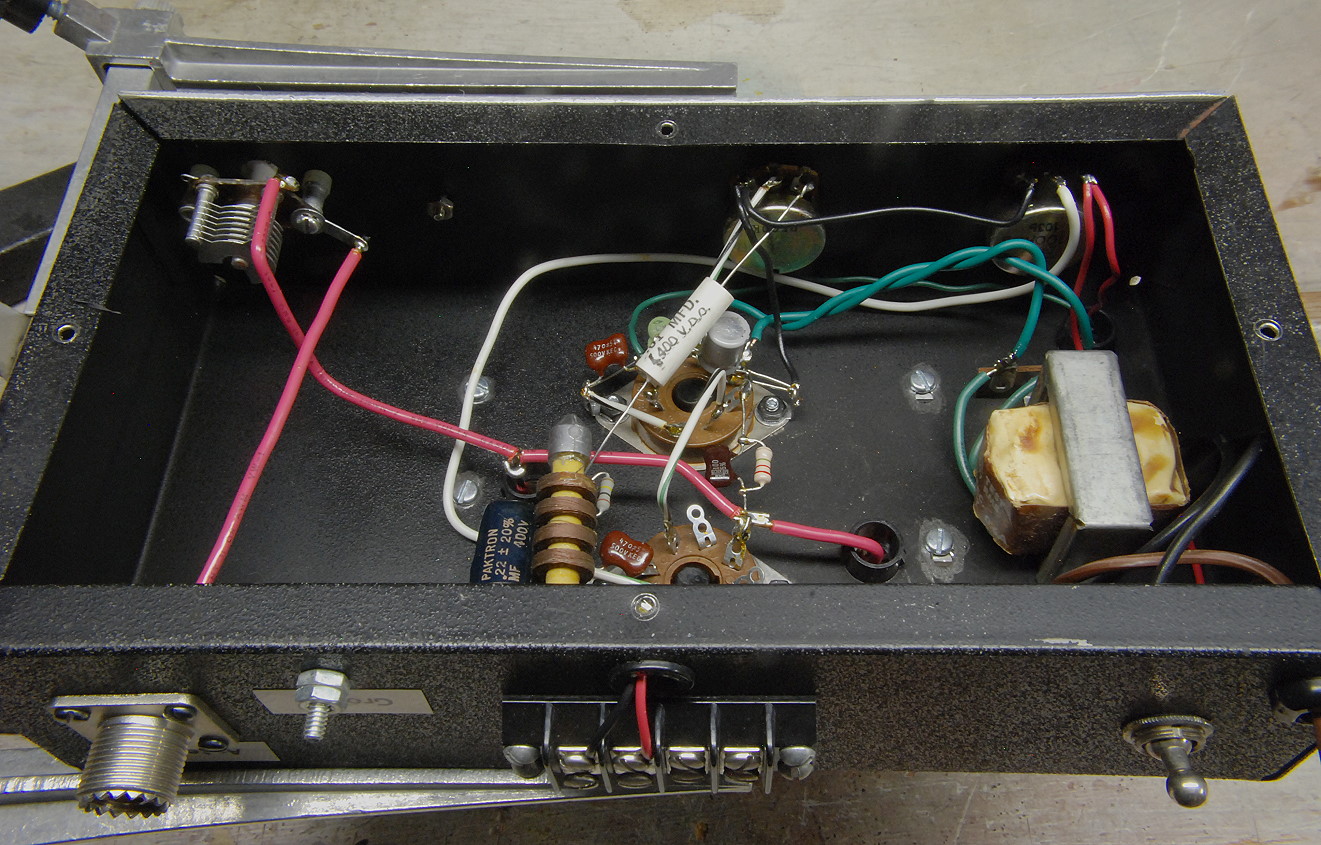
| Underchassis Side View: In this view underneath the chassis the filament transformer is visible at the top, and the filament power switch is visible at the top right. The regeneration control is at the top left, with the volume control just below it. At the extreme bottom left the antenna coupling capacitor can be seen. In the middle on the left is the tube socket, and the coil socket is on the right. The antenna connector is visible at the lower right. The pink wire in the photo is very heavy 12 gauge wire used to make the connections to the tuning capacitors and the antenna coupling capacitor. This wire is very stiff and greatly improves the tuning stability of the receiver when receiving CW and SSB signals. |
 Click on the image for a larger view. Click here for a super detailed view. |
| Underchassis Rear View: This is a picture underneath the chassis taken from the rear. The front panel is at the top in the photo. The antenna connector and antenna coupling capacitor are visible on the left, and the filament transformer and filament power switch are visible at the lower right. Note how the green leads that connect the filament transformer to the tube socket are twisted together to help minimize hum. The volume (on the left) and regeneration (on the right) controls can be seen mounted on the front panel at the top, and the tube socket (at top) and coil socket (at bottom) can be seen in the middle. The heavy pink wire that connects to the tuning capacitors passes through black plastic bushings in the top of the chassis. |
 Click on the image for a larger view. Click here for a super detailed view. |
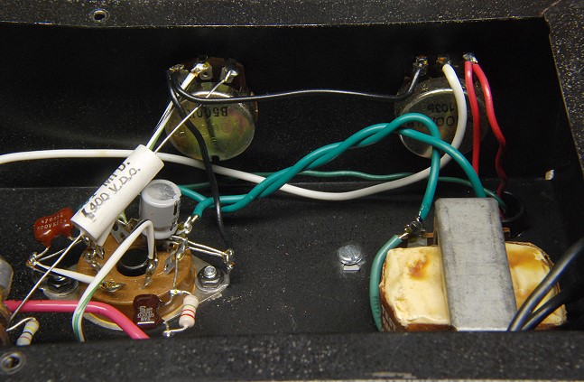
| Tube Socket and Volume and Regeneration Controls: This is a close-up taken from the same angle as the previous photo. The front panel is at the top and the rear panel is at the bottom. The tube socket can be seen at the left in the photo. The large white capacitor that passes over it and connects to the volume control is the audio coupling capacitor. The grey electrolytic capacitor directly to its right is part of the cathode bias circuit. The red 470 pf mica capacitor to the left of the white capacitor is the RF bypass capacitor. At top right is the regeneration control and the filament transformer is at the lower right. |
 Click on the image for a larger view. Click here for a super detailed view. |
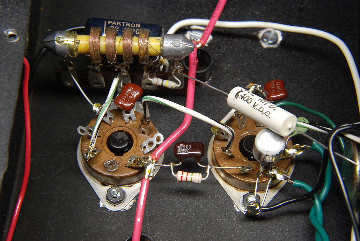
| Tube and Coil Sockets: In this picture the coil socket is on the left and the tube socket is on the right. Directly above the coil socket a terminal strip is used to hold several components. The largest of these is the 2.5 mH RF choke. Directly below the RF choke is a small, flat, red 470 pf mica capacitor. These two components form the plate decoupling circuit. Just above and behind the RF choke is a large blue 0.22 uf capacitor and just below the RF choke on its right is a 100 kohm (Brown-Black-Yellow) resistor. Both of these are part of the regeneration control circuit. In the middle of the photo connecting the coil socket to the tube socket are a dark red 100 pf mica capacitor and 2.2 Mohm (Red-Red-Green) resistor connected in parallel. These form the grid leak. The large white capacitor on top of the tube socket is the audio coupling capacitor. Directly above it is another red 470 pf mica capacitor that is the RF bypass capacitor. The grey capacitor underneath the white capacitor is part of the cathode bias circuit, and one of the green filament balance capacitors is barely visible behind the right end of the white capacitor. (The other filament balance capacitor was not installed at the time this picture was taken.) |
Click on the image for a larger view. Click here for a super detailed view. |
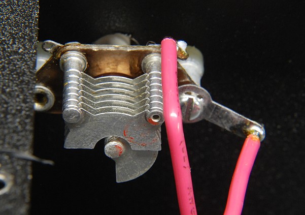
| Antenna Coupling Capacitor: This picture is a close-up of the antenna coupling capacitor. This capacitor has a minimum capacitance of 2 pf, and a maximum capacitance of 18 pf. In actual practice the entire range of the capacitor is used. Since both sides of the capacitor are above ground, the capacitor and capacitor shaft must be insulated from the chassis, and a plastic knob must be used on the shaft. My capacitor happened to have a plastic shaft, which is even better. To isolate it from the chassis, the capacitor is mounted to the front panel on white plastic standoff insulators which are just barely visible in the photo. The shaft passes through an oversized hole in the front panel. The oversized hole isn't really necessary with this capacitor, but is a must with a capacitor with a metal shaft. |
 Click on the image for a larger view. Click here for a super detailed view. |
 Back to Dr. Greg Latta's
Electrical Engineering and Amateur Radio Pages
Back to Dr. Greg Latta's
Electrical Engineering and Amateur Radio Pages
 If you have any questions or
comments, you can send E-Mail to Dr. Greg Latta at
glatta@frostburg.edu
If you have any questions or
comments, you can send E-Mail to Dr. Greg Latta at
glatta@frostburg.edu