
Twinplex Coil Set - Click for a closer view.
| Main Page and Exterior Photos | How To Operate A Regenerative Receiver |
| Interior Photos of the Receiver | Schematic Diagram and Circuit Description |
| L1 and L2 Coil Specifications | 6SN7 Dual Triode |
| Twinplex Receivers Built By Others | Modifications |
A General Comment On Winding Your
Coils:
Though exact specifications for the coils used in my receiver are given below,
it is not necessary to duplicate my coils exactly. The specifications are given
as an example only. Among other things, the frequency range covered by a coil
depends on the capacitors that are used in the tuning circuit, and it is very
doubtful that your tuning capacitor(s) will be the same as mine. Even if you
duplicated my coils exactly, the frequency range covered by each would thus be
different.
Making Your Own Coil Forms
The first problem in making a coil for your twinplex is finding a form for the
coil. Though coil forms are no longer manufactured, it is very easy to make
your own coil forms using readily available parts. For each coil form you will
need a 3/4" CPVC plumbing coupling and an 8-pin octal plug. The 8-pin plug
can be purchased at Antique Electronic
Supply or at a guitar shop or hamfest. The stock number at Antique
Electronic Supply is P-SP8-500. Get one of
these for each coil, and a few extras as well, as they are very handy. The CPVC
coupling has an outer diameter of 1 3/8", and is ideal for a coil
form. Sand the 8-pin octal plug down until it fits tightly into the
coupling and you now have an excellent coil form! See the photos below. There
is no need to glue the plug in if it fits snugly enough into the coupling. In
fact, it is better that you don't glue it in because then it is easy to
pull it back out should you decide to rewind the coil.. (Leave the octal plug
out of the coupling until you are finished making connections to it.)
 Click here for a larger image. 1" CPVC Coupling and 8-Pin Plug |
 Click here for a larger image. Completed Coil Form |
Wire:
I wound my shortwave coils with #22 solid insulated hookup wire with an outside
diameter (with insulation) of 0.056". For the AM coil I used #29 enameled
magnet wire with an outside diameter (with enameled insulation) of 0.013".
The coils are close wound with the turns touching each other. It is perfectly
fine to use the magnet wire for all of the coils if you like. You can also use
thinner wire (higher gauge number) for any of the coils, but if you do you
must space out the turns so that the winding is the length indicated in the
coil specifications table. You must use magnet wire
for the AM coil, otherwise you won't be able to fit enough turns on the coil.
Drilling Holes in the Coil Form and
Securing the wire:
The best way to drill holes through the coil form is to use a Dremel rotary
tool with a small keyless chuck on it. The Dremel stock number for the keyless
chuck is #4486. For windings that are made with magnet wire, the holes should
be slightly larger than twice the wire diameter so that the wire can
pass through the hole twice. When using hookup wire, the hole should be just
big enough for the wire to barely pass through once.
To tie off magnet wire, pass about 6" of magnet wire down through one
hole, up through the other, and then back down through the first hole, leaving
about 6" hanging out the bottom of the coil. To tie off hook up wire, pass
about 6" of wire through the hole and then bend it sharply down towards
the bottom of the coil form. The bend will hold it in place.
A Note On Stripping The Insulation From
Magnet Wire:
Magnet wire is coated with a thin insulation of clear enamel. This coating
must be removed in order to solder the wire or otherwise make a connection to
it. Some people try to scrape or sand the enamel off, and though this will
work, it is much easier if you note the following: First use a match or
lighter to heat the wire and burn off the insulation you want to remove.
Once burnt, fold a small piece of 320 grit sandpaper in half and sand off the
burnt insulation until clean, shiny copper is exposed. Quick and easy! Be
careful with smaller, fragile, magnet wire.
Winding the AM Coil:
You may want to try winding the AM coil first. Wind L2, the tickler winding,
first. Drill two small holes (big enough to let the wire pass through
twice) about 1/8" from each other, 3/8" from the bottom of the
coil form. Pass about 6" of magnet wire down through one hole, up through
the other, and then back down through the first hole, leaving about 6"
hanging out the bottom of the coil. While having an assistant hold the spool
of magnet wire to keep it taught, tightly wind 9 turns of wire spaced out
about 1/8". (If you are using #29 magnet wire, just wind the turns right
next to each other). Carefully drill two more holes at the end of the winding
and tie it off just like you did at the beginning of the winding, leaving
6" of wire hanging out the bottom. See the picture below of the finished
coil:

AM Coil
Now tackle the main winding, L1. Drill another pair of holes so that the main winding will start about 9/64" away from the top of the tickler winding. If the holes aren't in the right spot (like mine) you can adjust the first turn to get the correct spacing, as you can see in the picture above. Tie on the wire as before, and, winding in the same direction as before, wind 93 turns. Use an assistant again to keep the wire taught. (If you lose any tension in the wire, you will wind up with a real mess!) If you are using #29 magnet wire, close wind the turns next to each other. If you are using smaller wire, you must somehow space out the turns so that the winding is 1 7/32" long. While being careful to hold the winding in place, drill two more holes at the top of the winding and then tie off the winding as before. Place a dab of glue at the top and bottom of the winding to help to hold it in place.
Coil Connections:
Trim the wires so that about two inches (or as little as you can comfortably
get away with) extends out the bottom of the coil form. Strip about 1/2"
of insulation from the magnet wire as detailed above.
Finally, tin the leads and solder them to the pins of the octal plug as
follows:
The top of tuning coil
L1 (the larger winding) is connected to pin 8.
The bottom of L1 is connected to pin 2.
The top of tickler coil
L2 (the smaller winding) is connected to pin 4.
The bottom of L2 is connected to pin 6.
Winding Short Wave Coil SW4:
Four additional coils cover the short wave bands. Wind the SW-4 coil first, as
this is the easiest to wind. To wind L2, the tickler coil, first drill a hole
3/8" from the bottom of the coil form (two close together if you are using
magnet wire.) (See my earlier directions on drilling
holes in the coil form). Secure the wire to the hole(s). (See
how to secure the wire above). Now tightly wind 3
turns up the coil form. If you are using #22 hook up wire, just close wind the
turns. If you are using magnet wire, space out the turns so they occupy the
length listed in the table below. When you reach the end of the winding, drill
another hole (or holes) and tie off the wire.
To wind L1, the main winding, drill another hole (or holes) as close to the top end of L2 as you can. Secure the wire, and then wind, in the same direction, five turns of wire. If you are using #22 hook up wire, just close wind the turns. If you are using magnet wire, space out the turns so they occupy the length listed in the table below. Tie off the wire and pass it through the bottom of the coil form. See the photo of the SW-4 coil below to make sure you have wound the coil correctly:

Short Wave Coil SW4
The connections to the octal plug are the same as for the AM coil.. Strip
the insulation from the wires up to where they exit the bottom of the form, and
solder them to the following pins:
Bottom of L2: pin 6
Top of L2: pin 4
Bottom of L1: pin 2
Top of L2: pin 8
Insert the 8 pin plug into the bottom of the form. A photo of the completed
SW-4 coil is shown above. Try to keep the connections as short as
possible.
Winding Short Wave Coil SW1:
For SW1, the 1.6-3.0 MHz coil, start the tickler coil as close to the bottom of
the coil form as possible, without the octal plug interfering. When winding L1,
you will have to wind 38 turns. To make them fit, wind up 20 turns, snap back
down to the bottom again, and wind 18 more up over the previous 20 turns. (Do
not wind up 20 turns and then down 18!) If using magnet wire you don't need to
double layer the turns. Just be sure to space out the turns to the length
indicated in the table below. When winding the tickler turn, wind 4 turns, snap
back down to the bottom again, and wind 3 more up over the previous 4 turns.
(Do not wind up 20 turns and then down 3!) If you are using magnet wire, don't
double layer the turns, just space them out over the distance indicated in the
chart below. A photo of SW1 and all of the coils can be seen
here.
Winding the Other Short Wave
Coils:
The other short wave coils are wound in a similar manner to the AM coil using
the dimensions in the table below. If at all possible wind your coils so that
you can experiment with them and add or remove turns until they perform the way
you want. For example, when you wind L1, wind more turns than you think you
will need. Extra turns are relatively easy to remove, but adding turns is much
more difficult. The windings can be held in place temporarily with electrical
tape.
Until you are happy with any coil, use the minimum amount of solder to
solder the leads to the base pins. Don't fill the holes in the pins with solder
at this point. Just tack solder the leads to the ends of the pins. Don't
forget to remove the insulation before trying to solder it to the base pin!
To unsolder a lead, heat the pin while pulling on the wire from the inside with
a pair of needle nose pliers. If the pin fills with solder, heat it and then
quickly shake or blow out the solder.
Adjusting The Coils:
Removing turns from the
main winding L1 will
raise the lowest frequency tuned by L1. Adding turns will lower the
lowest frequency tuned by the coil. Turns should be added or removed from the
top of the coil so that the spacing between L1 and L2, and thus the
regeneration, is not affected.
If your receiver does not, overall, enter regeneration until the regeneration
control is turned quite far up, try adding a turn to the
tickler winding L2.
If your receiver, overall, squeals all the time or does not drop out of
regeneration until the regeneration control is turned way down, try removing a
turn from L2. The proper number of turns on L2 is a compromise, since many
things affect the regeneration, including the antenna, the antenna coupling,
and frequency of operation. Turns should be added/removed from the
bottom of L2 so the spacing between L1 and L2 is unaffected.
Finishing Off The Coils And Final
Soldering To The Base Pins:
When you are happy with the performance of a coil, drill new holes if necessary
to tie off the winding. Strip, tin, and solder the leads to the octal plug, and
fit the plug into the end of the coil form. A picture of the complete set of
finished coils can be seen below:
| Band | Approximate Frequency |
L1 | Length of L1 | L2 | Length of L2 |
| AM | 560-750 kHz w/padder 730-1550 kHz wo/padder |
93 turns #29 magnet wire close wound | 1.21" | 9 turns #29 magnet wire close wound | 0.12" |
| SW1 | 1.6-3.0 MHz | 38 turns #22 insulated hook up wire close wound* | 1.21" | 7 turns turns #22 insulated hook up wire close wound | 0.28" |
| SW2 | 3.1-6.8 MHz | 21 turns #22 insulated hook up wire close wound | 1.24" | 3 turns turns #22 insulated hook up wire close wound | 0.17" |
| SW3 | 5.6-12.2 MHz | 9.5 turns #22 insulated hook up wire close wound | 0.59" | 3 turns turns #22 insulated hook up wire close wound | 0.17" |
| SW4 | 8.9-19.9 MHz | 5 turns #22 insulated hook up wire close wound | 0.29" | 3 turns turns #22 insulated hook up wire close wound | 0.17" |
| Band | Frequency | L1 | L2 |
| AM | 560-750 kHz w/padder 730-1550 kHz wo/padder |
Loopstick | 2 turns close wound over lower end of loopstick |
| SW1 | 1.6-3.4 MHz | 40 turns close wound | 4 turns close wound 0.1" from L1 |
| SW2 | 3.3-6.5 MHz | 21 turns spaced out over 0.785" | 4 turns spaced out over 0.14' 0.1" from L1 |
| SW3 | 5.5-12 MHz | 10 turns spaced out over 0.360" | 3 turns spaced out over 0.095" 0.1" from L1 |
| SW4 | 9.3-20 MHz | 5 turns spaced out over 0.175" | 3 turns spaced out over 0.095" 0.1" from L1 |
Original Coil Forms And Wire:
The original short wave coils for the receiver were wound on coil forms that
have octal bases, a diameter of 1 1/4", and have ribs on them that keep
the windings spaced about 25 turns per inch. The last time I checked, these
forms were no longer commercially available. For these coils, I used #24 magnet
wire, available from Antique Electronic
Supply.
A Note On Stripping The Insulation From Magnet Wire:
Magnet wire is coated with a thin insulation of clear enamel. This coating
must be removed in order to solder the wire or otherwise make a connection to
it. Some people try to scrape or sand the enamel off, and though this will
work, it is much easier if you note the following: First use a match or
lighter to heat the wire and burn off the insulation you want to remove.
Once burnt, fold a small piece of 320 grit sandpaper in half and sand off the
burnt insulation until clean, shiny copper is exposed. Quick and easy!
Winding The Original Short Wave Coils:
L1 is wound at the top of the form and L2 is wound at the bottom of the form.
(In the schematic, L2 is shown at the top only for convenience.) L2 is spaced
about 1/10" from L1. It is very important that L1 and L2 be wound in
the same direction.
For SW1, the 1.6-3.4 MHz coil, I first had to glue a thin, smooth, piece of
plastic around the form to cover the ribs. This allowed me to close wind the
coil with each turn touching its neighbor. This permitted me to fit more turns
on the coil for more inductance.
If at all possible wind your coils so that you can experiment with them and add
or remove turns until they perform the way you want. For example, when you wind
L1, wind more turns than you think you will need. Extra turns are relatively
easy to remove, but adding turns is much more difficult. Space L2 about a tenth
of an inch from the bottom of L1, and leave some room at the bottom of L2 so
that you can add a turn or two if necessary. The windings can, at this point,
be held in place with black electrical tape, and the leads can be passed over
the top of the coil, and then down into the middle to connect to the base pins.
Keep all lead lengths as short as possible!
Until you are happy with the coil, use the minimum amount of solder to
solder the leads to the base pins. Don't fill the holes in the pins with solder
at this point. Just tack solder the leads to the ends of the pins. Don't
forget to remove the insulation before trying to solder it to the base pin!
To unsolder a lead, heat the pin while pulling on the wire from the inside with
a pair of needle nose pliers. If the pin fills with solder, heat it and then
quickly shake or blow out the solder.
Coil Connections:
The top of tuning coil
L1 is connected via pin 8 to the
grid leak and tuning
capacitors.
The bottom of L1 is connected via pin 2 to ground.
The top of tickler coil
L2 is connected via pin 4 to the
plate decoupling
circuit.
The bottom of L2 is connected via pin 6 to the plate of the detector triode.
Adjusting The Coils:
Removing turns from tuning coil L1 will
raise the lowest frequency tuned by L1. Adding turns will lower the
lowest frequency tuned by the coil. Turns should be added or removed from the
top of the coil so that the spacing between L1 and L2, and thus the
regeneration, is not affected.
If your receiver does not, overall, enter regeneration until the regeneration
control is turned quite far up, try adding a turn to the
tickler winding L2.
If your receiver, overall, squeals all the time or does not drop out of
regeneration until the regeneration control is turned way down, try removing a
turn from L2. The proper number of turns on L2 is a compromise, since many
things affect the regeneration, including the antenna, the antenna coupling,
and frequency of operation.
Finishing Off The Coils And Final Soldering To The Base
Pins:
When you are happy with the performance of a coil, carefully rewind the coil
and use tape to keep the turns tightly in place. Drill a tiny hole right at the
end of each winding so that the wire can pass through the side of the form with
minimum extra length. You can then pull the wire through the hole, tighten the
winding, and pass the wire down through the base pin. Add a dab of hot melt
glue to secure the wires at each hole.
Snip the wire off about 1/2" past the end of the base pin. Carefully
remove the enamel from the end of the wire by burning it off with a match and
scraping/sanding off the residue until bright copper is exposed. Push the wire
back in just far enough to solder it to the pin, and snip off the excess.
AM Coil:
My original AM coil uses the same coil form as the short wave coils, but is
made a little differently from them. This coil uses a ferrite core loopstick
for L1. Mine was salvaged from an old AM radio. It is a bit long and sticks up
out of the coil form, but it works great.
The tickler coil L2
consists of a couple of turns close wound over the bottom end of the loopstick.
Be sure that you wind the tickler coil in the same direction that the wire
on the loopstick is wound!
You should not have to add or remove turns to adjust the loopstick itself. It
has already been designed to tune to the bottom of the AM band with a tuning
capacitor having a maximum capacity of about 365 pf. If your tuning capacitor
does not have enough capacitance, the extra capacitance can be obtained by
adding a padding capacitor temporarily in
parallel with the tuning capacitor to make up the difference.
You may have to adjust the tickler coil as detailed above by adding or removing
a turn or two.
When you are finished testing the combination and are satisfied that it works
OK, solder the leads permanently to the base and use some hot melt glue to glue
the end of the loopstick to the base.
| Original Complete Coil Set: This is a picture of all five original coils. The AM coil with its loopstick sticking out the top is on the left, followed by coils SW1, SW2, SW3, and SW4 respectively. SW1, second from left, is covered first with smooth plastic and then close wound. Note that the tickler coil coil is wound at the bottom of each form, even though it is shown at the top in the schematic. |
 Click on the image for a larger view. Click here for a super detailed view. |
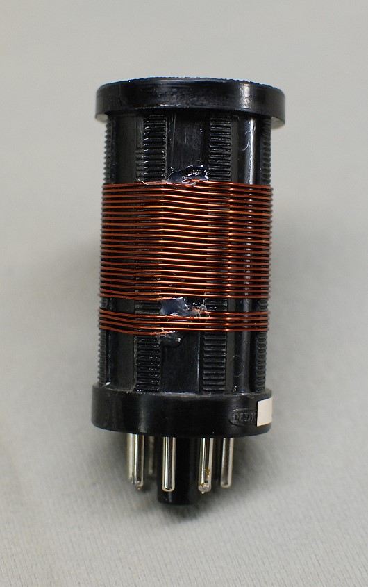
| Original Coil SW2 Front - Close Up: In this close up of my original SW2 coil, you can see the ribs on the coil form that hold the wire in place. The tickler coil is spaced three ribs below the bottom of the upper coil, L1. This puts it roughly 1/10" away from L1. |
 Click on the image for a larger view. Click here for a super detailed view. |
| Original Coil SW2 Rear - Close Up: In this picture of the other side of my original SW2 coil, you can see how the wires from the windings pass through small holes drilled through the side of the coil from. A small dab of hot melt glue is used at each hole to secure the wire and keep the windings tight. |
 Click on the image for a larger view. Click here for a super detailed view. |
 Back to Dr. Greg Latta's
Electrical Engineering and Amateur Radio Pages
Back to Dr. Greg Latta's
Electrical Engineering and Amateur Radio Pages
 If you have any questions or
comments, you can send E-Mail to Dr. Greg Latta at
glatta@frostburg.edu
If you have any questions or
comments, you can send E-Mail to Dr. Greg Latta at
glatta@frostburg.edu