
| Main Page and Exterior Photos | How To Operate A Regenerative Receiver |
| Interior Photos of the Receiver | Schematic Diagram and Circuit Description |
| L1 and L2 Coil Specifications | 6SN7 Dual Triode |
| Twinplex Receivers Built By Others | Modifications |
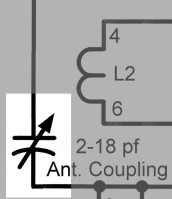
| Antenna Coupling Capacitor: The antenna coupling capacitor is a critical component in a regenerative receiver without an RF stage, like the Twinplex. In such a receiver, the antenna is an integral part of the regenerative detector, and for proper operation the coupling to the antenna must be easily adjustable. Increasing the capacitance increases the coupling and vise versa. Both sides of the capacitor are above ground, so it is necessary to insulate the frame of the capacitor from the chassis. For more information on how to adjust the antenna coupling, see my page on How to Operate a Regenerative Receiver. |
 |
| Tuning Circuit: After passing through the coupling capacitor, the signal is applied to a parallel resonant circuit consisting of L1 and the bandset and bandspread capacitors. The resonant circuit shorts to ground all signals except that to which the circuit is tuned (resonant frequency.) The resonant frequency is determined by the inductance of L1, which can be changed by switching coils, and the settings of the bandset and bandspread capacitors. The bandset capacitor is used to set the portion of the band you wish to tune, and the bandspread is then used for the fine tuning. Because the antenna is part of the detector circuit, changing the antenna or the antenna coupling also affects the frequency to which the receiver is tuned. This is one of the shortcomings of this type of circuit. For more information on this, see my page on How to Operate a Regenerative Receiver. |
 |
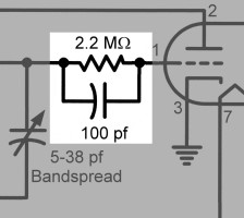
| Grid Leak: The output of the resonant circuit is coupled to the grid of the first triode through a 100 pf capacitor. The grid and cathode of the triode function as a diode and rectify the signal, much as the crystal diode does in a crystal radio. The rectifying action puts a negative charge on the grid, and this charge would build up and eventually make the grid so negative that the tube would be cut off. To prevent this, the 2.2 Megohm resistor bleeds some of the charge off, leaving a small negative voltage (grid bias) on the grid. The grid bias helps to prevent the tube from loading the tuned circuit, which would lower the selectivity. |
 |
| Tickler Coil: The tickler coil L2 is the part that distinguishes a regenerative detector from all others. The amplified signal in the plate of the tube passes through the tickler coil, which is wound in close proximity to the tuning coil L1. The two coils form a transformer, and some of the amplified signal in the plate circuit is fed back in phase to the input circuit. This positive feedback, or regeneration, gives the detector its name and takes place over and over again, amplifying the signal many times over that which would normally occur. This allows a huge amount of amplification to take place in a single stage. The tickler coil must be connected with the proper polarity, otherwise the feedback reduces, rather than increases, the gain. A common mistake in constructing a regenerative receiver is to connect the tickler coil backwards. If your receiver does not want to regenerate properly, try reversing the connections to the tickler coil. |
 |
| Regeneration Control Circuit: Too much regeneration is as bad as too little, so the regeneration must be adjustable. There are several ways to do this, but in the Twinplex the plate voltage of the detector is varied to control the regeneration. The regeneration control is a potentiometer connected between B+ and ground. Changing the position of the wiper changes the plate voltage of the detector. Since the wiper can generate some noise, and since the detector can greatly amplify the noise, a 0.22 uf capacitor is connected between the wiper and ground to short circuit the noise to ground. The 100 kohm resistor prevents the 0.22 uf capacitor from shorting the audio in the plate of the detector to ground. |
 |
| Plate Decoupling Circuit: The signal in the plate circuit consists of the amplified RF signal along with the detected audio. The plate decoupling circuit allows the audio to pass through, while blocking the RF. The reactance of the 470 pf capacitor is very low at RF, effectively grounding one end of the tickler coil for RF and completing the plate circuit for RF. Without this capacitor, the receiver will not regenerate. At the same time, the reactance of the capacitor is much higher at audio frequencies, keeping them from flowing to ground. On the other hand, the reactance of the 2.5 mH RF choke is low at audio frequencies, allowing them to pass through to the next stage, while its high reactance at radio frequencies prevents them from passing through. |
 |
| Volume Control and Audio Coupling
Capacitor: The 0.01 uf capacitor blocks the plate voltage of the detector tube while allowing the audio to pass though to the volume control. The volume control functions as an adjustable voltage divider that picks off a portion of the audio and applies it to the grid of the second triode. |
 |
| Cathode Bias: To prevent distortion, the grid of the second triode must be kept slightly negative with respect to the cathode. This is accomplished by inserting a 1 kohm resistor in series with the cathode. As current flows to the cathode, it causes a voltage drop across the resistor which biases the tube. To allow audio to flow around the resistor, a 47uf/10V electrolytic capacitor is connected in parallel with it. |
 |
| RF Bypass Capacitor: The amplified audio appears at the plate of the second triode. Since this triode is relatively near the first triode inside the tube, it might be capacitively coupled to the first stage at radio frequencies, and some RF may unintentionally appear at the plate of the second triode. The 470 pf capacitor shorts this RF to ground and prevents it from causing any problems. |
 |
| Filament Balance Capacitors: The 6SN7 tube requires 6.3 V at 0.6 A for the filaments. This could be supplied by batteries, but it is much easier to use a filament transformer. The problem with using a filament transformer is that the gain of the regenerative detector is so high that the slightest hum in the circuit may be greatly amplified, often producing objectionable hum in the output. Even if the hum cannot be heard in the headphones because of poor frequency response, it can affect regeneration and the reception of weak signals. Hum is produced partly by thermal effects but also by capacitive coupling between the cathode of the tube and the filament. Though this coupling is very small, in a regenerative receiver it can be sufficient to cause hum in the output. The solution, other than using DC on the filaments, is to balance the filaments for RF. The 0.01 uf capacitors are an open circuit for the filament voltage but act as a short circuit for RF. It is important that both capacitors be used. Using both capacitors places the center of each triode filament at exact ground potential for RF, greatly reducing the hum in the receiver. |
 |
 Back to Dr. Greg Latta's
Electrical Engineering and Amateur Radio Pages
Back to Dr. Greg Latta's
Electrical Engineering and Amateur Radio Pages
 If you have any questions or
comments, you can send E-Mail to Dr. Greg Latta at
glatta@frostburg.edu
If you have any questions or
comments, you can send E-Mail to Dr. Greg Latta at
glatta@frostburg.edu
This page is under constant revision. Please check back often.