
Modified Twinplex - Click for a closer view.
| Introduction |
| Battery Switch and Audio Output Transformer |
| Line Cord, Power Switch, and Fuse |
| New AM Coil |
Introduction:
When I first built my Twinplex, I had a great time using it, but as time passed
it became apparent that I would need to change several things:
1. The battery would run down if I didn't disconnect it when not using the
Twinplex. A switch to do this, mounted on the chassis, would be better than
prying the connector off of the battery each time.
2. I always used an audio transformer with my Twinplex so I could use modern,
low impedance, headphones. The transformer sat on the table in front of the
Twinplex and was rather ugly. Permanently mounting the transformer on the
chassis would be a much better option.
3. The line cord I used when I built the Twinplex was ungrounded and I hadn't
used a fuse. I decided it was time to replace the old cord with a grounded cord
and to add a fuse.
4. The original AM coil used a ferrite loopstick. The coil worked great, but
loopsticks were no longer readily available. I wanted to design an AM coil that
didn't use a loopstick so that it could easily be duplicated by others.
After performing these modifications, I found that the Twinplex was a real pleasure to use, and, by moving some of the outboard accessories to the chassis, the receiver also looked much better..
Battery Switch and Output Transformer: To avoid having to connect and disconnect the battery, a toggle switch was mounted in series with the positive battery lead and mounted on the back panel. I had a small surplus audio output transformer and I mounted it on the top of the chassis. It can be seen at right in the photo. The primary of the transformer is wired to where the headphones were originally connected, and the secondary of the transformer then runs to the headphone terminals. Note that the transformer leads run through grommeted holes in the chassis. If you can't find an actual audio output transformer, try using a small 6.3 volt filament transformer. I found that a 6.3V, 0.6A transformer I had on hand made an excellent audio matching transformer. (The 120V primary is also the audio primary, and the 6.3V secondary connects to the headphones.) In this photo the new line cord, filament power switch, battery switch, and fuse holder can be seen clustered together on the left side of the back panel. |
Click on the image for a larger view. Click here for a super detailed view. |
Line Cord, Power Switch, and Fuse: I purchased an 18/3 grounded cord at a hamfest and also a bag full of fuse holders. I was very lucky in that I was able to reuse the old cord strain relief and chassis hole without any modifications. I mounted the fuse holder at the bottom of the back panel between the filament power switch and battery switch. In this picture the filament power switch is on the back panel on the left and the battery switch is on the back panel in the center. The filament transformer is at the lower left. The fuse holder can be seen at top between the two switches. Since the filament draws very little power, I used a 1/4A fuse. The white neutral lead from the new power cord is connected to one lead of the filament transformer using a terminal strip lug that is just visible above the transformer. The green ground lead from the power cord is connected to the chassis via a terminal strip lug that can be seen at the right. The black hot lead from the power cord is connected to the center lug on the fuse holder. A black lead from the side fuse holder lug is connected to the top of the filament power switch at left. The remaining filament transformer lead is connected to the bottom of the filament power switch and cannot be seen in the photo. Though the receiver will work regardless of the order in which the fuse and switch are connected, safety concerns require that the hot AC lead goes to the fuse first, then to the switch, and then to the transformer. The line cord, fuse holder, filament power switch, and battery switch can also be seen clustered together on the left side of the back panel in the photo above. |
 Click on the image for a larger view. Click here for a super detailed view. |
New AM Coil: It took some experimenting to come up with a new AM coil for the Twinplex, but the new coil can be easily made using readily available components. The new coil consists of a main winding of 93 close wound turns of #29 enameled magnet wire and a tickler winding of 9 close wound turns of #29 enameled magnet wire. For complete instructions on making the new AM coil, click here. |
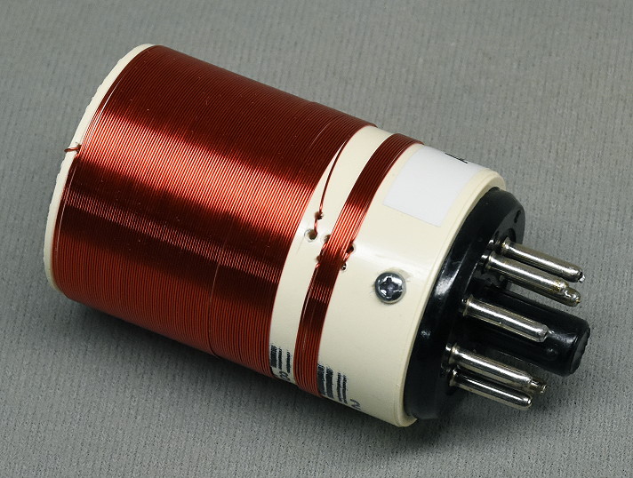 Click on the image for a larger view. |
 Back to Dr. Greg Latta's
Electrical Engineering and Amateur Radio Pages
Back to Dr. Greg Latta's
Electrical Engineering and Amateur Radio Pages
 If you have any questions or
comments, you can send E-Mail to Dr. Greg Latta at
glatta@frostburg.edu
If you have any questions or
comments, you can send E-Mail to Dr. Greg Latta at
glatta@frostburg.edu