
Click Here For A Larger View
Important Safety Note: Working on or testing equipment such as the 813 amplifier and its matching power supply is extremely dangerous since very high voltages are present when the equipment is turned on, and may even be present when the equipment is turned off and unplugged. If at all possible, do all work with the equipment off and unplugged and be sure that the capacitors are properly discharged before working on the equipment. The operator assumes all risk and liability in such matters! Do not work on this type of equipment unless you are experienced with working around very high voltages!
Circuit Design Considerations:
The Wingfoot 813 amplifier power supply was designed and built partly by Jim
Trutko, W8EXI, and me. The chassis work, transformer and choke mounting for the
screen/plate supply, and much of the wiring was done by Jim. I am responsible
for critical design and safety changes, the front panel labeling, repairs, all
of the new rectifiers, all of the new filter capacitors and bleeder resistors,
and the new transformer. The power supply was primarily designed to go with the
Wingfoot 813 amplifier, but it was also
designed to be versatile and to perhaps be used with other amplifiers. As such
a variety of output voltages are available simply by changing switches on the
front panel. The power supply is very conservatively rated and can supply much
more power than needed by the 813
Amplifier. Nominal output of the power supply when used with the
813 Amplifier at 250W output is 2240 volts
DC at about 160 mA. The bias supply can deliver up to -150 volts DC at about 30
mA.
Important Note:
In July of 2013 one of the original Thordarson transformers shorted out. As a
result, both of the original Thordarson transformers were replaced with a
single, modern, transformer purchased from Ameritron. This radically altered the
exterior appearance of the power supply, as can be seen in the photos below.
However, the underside appearance of the power supply did not change
significantly, so the photos of the underside of the power supply below were
left unchanged and are pictures of the original power supply. Some parts of the
original wiring did not change, and are labeled below as "Old/New Power
Supply". Others did change, and are labeled as "Old Power
Supply". Comments for the old pictures that pertain to the transformer
upgrade are marked in italics.
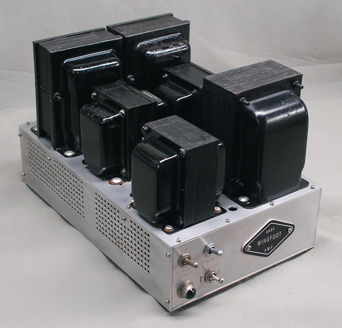
| Old Amplifier Power Supply - Front View: The power supply for the amplifier is a real beast. Weighing in at a hefty 44 lbs, it is a beautiful example of engineering to make use of what you have. The plate supply consists of three full wave, choke input power supplies run in series to obtain the 2000 volt plate potential needed for the 813. One supply has an output of approximately 450 volts under load, while the other two full wave supplies each have an output of 800 volts under load. The two 800 volt supplies have dual primaries which can be run in series or parallel, as determined by a front panel switch. This permits operation at reduced plate voltage for tune up purposes. The 450 volt supply can also be used as a screen grid supply, though in this amplifier the 813 screen grid is connected in parallel with the control grid and the tube is run as a high-u triode. A regulated bias supply is also included. |
 Click on the image for a larger view. Click here for a super detailed view. |
| New Amplifier Power Supply - Rear/Side View: During July of 2013, after 50 or 60 years of fine service, one of the Thordarson plate transformers shorted internally, ruining the transformer. Since there were two of these transformers, it was decided to replace both of them with a single, larger, transformer. After some research, a stock transformer available from Ameritron was selected. This transformer, Ameritron stock number 406-1532, is the same as the one used in the popular Ameritron AL-811 and AL-811H amplifiers. The transformer ratings were 1500V AC at 500mA, 12V AC at 1A, and 6.5V AC at 16A. Normally made to power a 600W output amplifier using four 811A tubes, this transformer was very conservatively rated for this application, especially since the 6.5V filament winding would not be used. The old Thordarson transformers were removed, along with their associated filter chokes. The two 800V DC full wave/center tap, choke input power supplies were replaced with a single, full wave/bridge, capacitor input power supply. The 400V DC plate/screen supply was left unchanged. The new transformer can be seen on the left in the photo. The transformer and choke for the 400V plate/screen supply can be seen on the right.. |
Click on the image for a larger view. Click here for a super detailed view. |
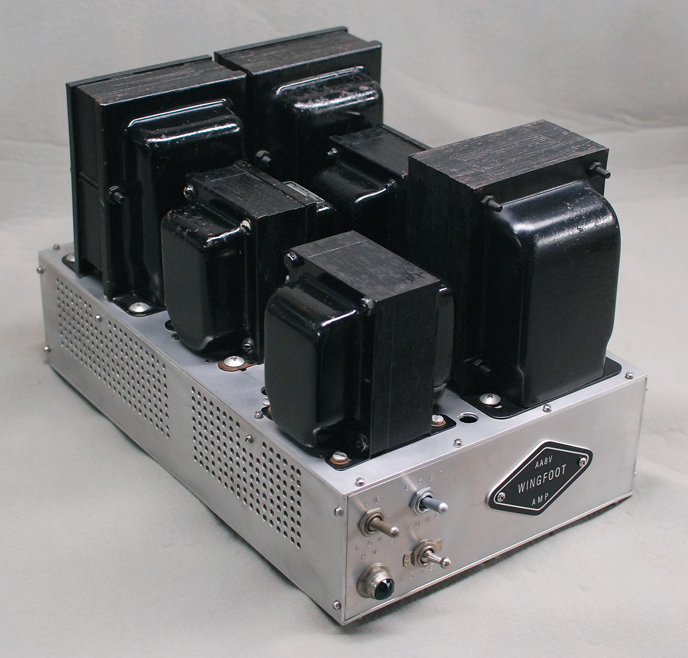
| Old Amplifier Power Supply - Second Front View: In this front view of the power supply the various chokes and transformers are easily identified. At the front on the right is the screen/plate/bias transformer, T3. This is the largest of the three transformers and has three secondaries. One is used for of the plate/screen supply, the second is used for the bias supply, and the third, a 6.3V AC filament winding, is used for the pilot light. On the front on the left is the Stancor C-1402 swinging filter choke used in the 450 volt screen/plate supply. Two more C-1402 chokes are in the middle of the chassis. These are used in the two 800V plate supplies. At the rear are the two Thordarson 16-P-00 transformers, T1 and T2, used in the two 800 volt plate supplies. |
 Click on the image for a larger view. Click here for a super detailed view. |
| New Amplifier Power Supply - Front View: In this front view of the new power supply, the new Ameritron transformer can be seen in the back, and the 400V plate/screen supply power transformer and choke can be seen at the front. Compare this to the photo above, and you can see the changes that were made. The weight of the new transformer is about the same as the combined weight of the two old transformers, but since two power supply chokes were also eliminated, the power supply weighs much less than it used to. With the new transformer the total power supply output with a nominal 160mA load increased from 1900V to about 2240V. As a result, the 813 amplifier puts out much more power than previously and/or requires much less drive than before for the same output. The performance increase is substantial and makes the cost and effort of replacing the old transformers worthwhile. |
 Click on the image for a larger view. Click here for a super detailed view. |
| Old Amplifier Power Supply - Side View: In this side view of the power supply the two plate transformers T1 and T2 are on the left, the plate filter chokes are in the middle, and the screen/plate supply power transformer T3 and filter choke are on the right. The 0B2 and 0A2 bias voltage regulator tubes are mounted between the two filter chokes in the front. |
 Click on the image for a larger view. Click here for a super detailed view. |
| New Amplifier Power Supply - Side View: In this side view of the power supply the Ameritron transformer is visible on the left and the screen/plate supply power transformer T3 and filter choke are on the right. The 0B2 and 0A2 bias voltage regulator tubes are mounted just to the left of the filter choke. If you compare this to the photo above, you can see the changes that were made when the old Thordarson plate transformers were replaced with the modern Ameritron transformer. |
 Click on the image for a larger view. Click here for a super detailed view. |
| Old Amplifier Power Supply - Rear View: This is a view of the power supply from the back. Transformers T1 and T2 are now at the front of the photo, and you can even read the labels on them in the super detailed view. The plate/screen/bias supply transformer, T3, is in the back on the left. |

Click on the image for a larger view. Click here for a super detailed view. |
| Old/New Amplifier Power Supply - Rear Panel Close-Up:
This is a close-up of the rear panel on the power supply. The black and red plate voltage connectors (James Millen Type 37001) are at the top on the left. The yellow connector below them (also James Millen type 37001), originally intended for the screen voltage connection, is not used. The male Amphenol MS style connector on the right is for the AC power cord. The blue connector is for bias voltage, and the light brown connector at center is for bias and/or screen voltage. These connectors are relatively expensive, but provide the most secure connection possible. Although there are three fuse holders on the back panel, only the fuse on the right is used. The others were originally included for possible 240 volt operation, but were never used. With the transformer upgrade, the only change to the back panel was that two of the fuse holders are now used. The fuse holder on the right is for the 6A main fuse, the middle fuse holder is for 1A the inrush circuit fuse, and the left fuse holder is for a spare 6A fuse. |
 Click on the image for a larger view. Click here for a super detailed view. |
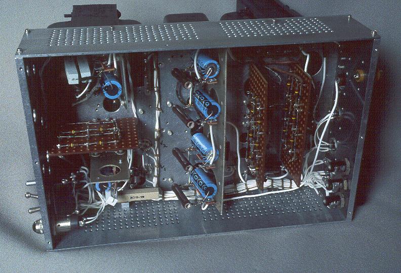
| Old Amplifier Power Supply - Underside: Since the amplifier power supply is actually four power supplies on one chassis, it gets quite crowded underneath. The 450 volt supply is at the upper left, and the bias supply is at the lower left. The two 800 volt supplies occupy the right side of the chassis. The 450 volt supply and the two 800 volt supplies are connected in series to proved the 2000+ volts needed for the 813 plate. White teflon insulated wire is used throughout the power supply. The circuit board at left is the rectifier stack for the 450 volt supply, and the two circuit boards at right are the rectifier stacks for the two 800 volt supplies. All of the power supplies, except for the bias supply, use choke input filtering, which provides much better voltage regulation and turn on surge protection than capacitor input filtering. Replacement of the old plate transformers with a single unit required some changes to the underside of the power supply which are not easily visible in photographs. The rectifier stacks were modified to produce a full wave bridge rectifier and the capacitors were wired together into a single capacitor bank. A new current inrush circuit was also added to protect the rectifiers. This photo shows the underside before the transformer upgrade. |
 Click on the image for a larger view. Click here for a super detailed view. |
| Old Amplifier Power Supply - Underside (Before
Redesign): When the power supply was originally restored, only five filter capacitors and bleeder resistors were used. The bleeder resistors were later replaced with higher resistance units to lower the standby heating in the power supply. Standby power dissipation was lowered from 37 watts to less than 10 watts. However, as a side effect, the standby voltage on the capacitors rose above the maximum 450 volt rating for the filter capacitors. 500 volt capacitors of sufficient capacity were not available, so each 450 volt, 47uf capacitor was replaced with two 350 volt, 100uf capacitors in series, the equivalent of a 700 volt, 50uf capacitor. Each capacitor was then shunted with a 75k ohm bleeder/equalizing resistor. The result was slightly more capacitance with a much higher voltage capability. This picture was taken before the old capacitors and bleeder resistors were replaced. The old capacitors are blue in the photo at right and the bleeder resistors are brown ceramic wirewound units. Compare to the photo above taken after the redesign. |
 Click on the image for a larger view. Click here for a super detailed view. |
| Old/New Amplifier Power Supply - Filter Capacitor
Close-up: A total of ten 100uf, 350 volt capacitors (black) are used in the 813 amplifier power supply. Each of these is shunted with a 75k ohm, 3 watt bleeder resistor (blue). The capacitors and bleeder resistors are mounted in pairs on terminal strips. Four are used in each 800 volt plate supply, and two are used in the 450 volt screen/plate supply. The capacitors must have plenty of reserve voltage capability since the voltage across them during no load is much higher than under full load. The filter capacitors were left essentially unchanged when the old plate transformers were replaced with a single transformer. A simple wiring change turned them into a single, 2800V, 12.5uF capacitor bank. |
 Click on the image for a larger view. Click here for a super detailed view. |
| Old Amplifier Power Supply -
Rectifier Stack Close-up: Double-sided circuit boards are used for the rectifier stacks for each supply. For each 800 volt supply, fourteen 1N4005 silicon diodes (seven for each side of the full wave center-tapped circuit) are strung in series, each shunted by a 120k resistor to equalize the reverse voltage drops. Seven diodes and seven equalizing resistors are mounted on each side of the circuit boards. Note that each diode and its associated equalizing resistor are mounted on opposite sides of the circuit board. The original diodes were surplus, unmarked, "top hat" style diodes (see the bias circuit below), but several of these failed after a short time. They were all replaced with the 1N4005 diodes. The newer diodes have much larger PIV ratings and much larger peak current capabilities. When the old Thordarson plate transformers were replaced with a single, modern, Ameritron transformer, the rectifiers on one of the circuits boards were all reversed, and the boards were wired together to form a single, full wave, bridge rectifier. No other changes were needed. |
 Click on the image for a larger view. Click here for a super detailed view. |
| Old/New Amplifier Power Supply - Bias
Supply, Power Switch, and Screen Rectifier Stack Close-up: The bias supply is a simple half wave supply that feeds a pair of voltage regulator tubes in series. Two top hat diodes are used in series in the supply, each shunted by a 150k equalizing resistor. These are the same kind of diode that were originally used in the plate supplies. In this photo you can see the two top hat diodes to the right of the blue 22uf filter capacitor, which is shunted by a white 47k bleeder resistor. The brown 2k power resistor at the bottom in the photo is the dropping resistor for the voltage regulator tubes. At the top of the photo the plate/screen supply rectifier stack can be seen. The construction of the plate/screen rectifier stack is the same as the plate rectifier stacks, except that five diodes are used each side of center tap, rather than seven. The power switch and pilot light can be seen on the left in the photo, and the 7 pin voltage regulator tube sockets are visible on the right. This section of the power supply was unaffected by the transformer upgrade. |
 Click on the image for a larger view. Click here for a super detailed view. |
 Back to Dr. Greg Latta's
Electrical Engineering and Amateur Radio Pages
Back to Dr. Greg Latta's
Electrical Engineering and Amateur Radio Pages
 If you have any questions or
comments, you can send E-Mail to Dr. Greg Latta at
glatta@frostburg.edu
If you have any questions or
comments, you can send E-Mail to Dr. Greg Latta at
glatta@frostburg.edu
This page is under constant revision. Please check back often.