| Main Page and Front and Side Views | Tank Coil Information |
| Interior and Back Views | Typical Operating Conditions |
| Circuit Description and Schematic Diagram | Power Supply Photos |
| 813 Tube Information | Power Supply Circuit Description and Schematic Diagram |
Tank Coil Information
At the request of several people, I have provided information on the tank
coil used in the Wingfoot 813 Amplifier..
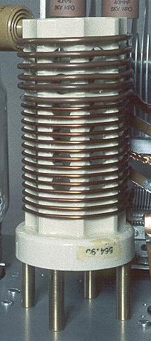
As can be seen in the photo, the coil is wound on a ceramic form with a
diameter of 2 1/10 inches and consists of 5 2/3 turns of #8 copper wire spaced
out over 1 1/4 inches followed by 14 turns of #12 copper wire spaced out over 2
5/16 inches.
The two coil sections are soldered directly to each other to make one
continuous coil.
The #8 section of the coil is the plate end and the #12 section of the coil is
the antenna end.
Taps are made at 2T, 3T, 5T, 8T,10T, and 20T from #8 or plate end of the coil.
(T=Turns) The 20T tap is really just the whole coil. The taps at 2T, 3T, and 5T
are on the #8 wire, and the other taps are on the #12 wire. (The taps can't be
seen in the photo above since they are on the other side of the coil.)
The proper tap to use for each band is best determined by experiment. The taps
given here just provide a wide variety, and the number of taps was chosen to
match the number of positions on the band switch. I suggest that you initially
make the taps movable/temporary and find the correct taps by experimentation. A
large alligator clip could be used as a temporary tap. (BE SURE TO TURN THE
POWER OFF AND LET THE PLATE VOLTAGE DRAIN OFF COMPLETELY BEFORE TRYING TO
CHANGE A TAP!!!) Once the proper taps are found, they can then be soldered and
made permanent.
When first built, the amplifier only operated on the 40m, 30m, and 20m bands.
The original tank coil lacked sufficient inductance to tune the 80m band. 80m
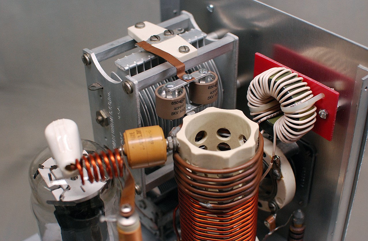
capability was added to the amplifier some years later by adding a toroidal
inductor (L1) in series with the original tank coil. The inductor was made by
winding 30 turns of #18 insulated wire on a T-184-6 (yellow) form. The inductor
was then mounted on the back of the front panel using a piece of plastic sheet
and a couple of cable ties, as can be seen in the photo below:

Click on the image for a larger view.
Click here for a super detailed
view.
Note that the toroidal inductor alone does not tune 80m. It is the combination of the original coil and the toroidal inductor in series that tunes 80m.
 Click here for pictures and information on the matching Wingfoot VFO
2E26 Exciter
Click here for pictures and information on the matching Wingfoot VFO
2E26 Exciter Back to Dr.
Greg Latta's Electrical Engineering and Amateur Radio Pages
Back to Dr.
Greg Latta's Electrical Engineering and Amateur Radio Pages
 If you have any questions or
comments, you can send E-Mail to Dr. Greg Latta at
glatta@frostburg.edu
If you have any questions or
comments, you can send E-Mail to Dr. Greg Latta at
glatta@frostburg.edu