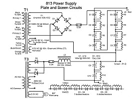
 Plate and Plate/Screen Supply |
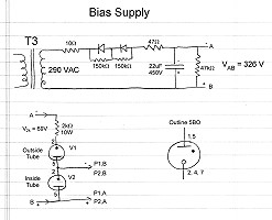 Bias Supply |
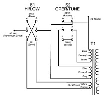 Transformer T1 Primary Wiring |
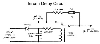 Inrush Delay Circuit |
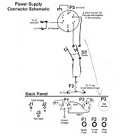 Power Connector Wiring |
| Main Page and Front and Side Views | Typical Amplifier Operating Conditions |
| Interior and Back Views | Tank Coil Information |
| Amplifier Circuit Description and Schematic Diagram | Power Supply Photos |
| 813 Tube Information | Power Supply Circuit Description and Schematic Digram |
| Plate and Plate/Screen Supply |
Bias Supply |
| Transformer T1 Primary Wiring |
Inrush Delay Circuit |
| Power Connector Wiring |
Circuit Design Considerations:
The Wingfoot 813 amplifier power supply was designed and built partly by Jim
Trutko, W8EXI, and me. The chassis work, transformer and choke mounting, and
most of the wiring was done by Jim. I am responsible for critical design and
safety changes, the front panel labeling, repairs, all of the new rectifiers,
and all of the new filter capacitors and bleeder resistors. The power supply
was primarily designed to go with the Wingfoot
813 amplifier, but it was also designed to be versitile and to perhaps be
used with other amplifiers. As such a variety of output voltages are available
simply by changing switches on the front panel. Nominal output of the power
supply is 2240 volts DC at about 160 mA, 450 volts DC at about 45 mA, and up to
-150 volts DC at about 30 mA.
 Back to Dr. Greg Latta's
Electrical Engineering and Amateur Radio Pages
Back to Dr. Greg Latta's
Electrical Engineering and Amateur Radio Pages
 If you have any questions or
comments, you can send E-Mail to Dr. Greg Latta at
glatta@frostburg.edu
If you have any questions or
comments, you can send E-Mail to Dr. Greg Latta at
glatta@frostburg.edu