| Main Page and Front and Side Views | Tank Coil Information |
| Interior and Back Views | Typical Operating Conditions |
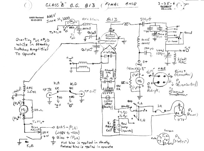
| Circuit Description and Schematic Diagram | Power Supply Photos |
| 813 Tube Information | Power Supply Circuit Description and Schematic Diagram |
The Wingfoot 813 amplifier was designed and built by me to match the W8EXI Wingfoot VFO Exciter. At the time I received the exciter from Jim Trutko, W8EXI, I also received an amplifier that Jim had been working on years earlier. Designed around the popular (in the 1950's) 813 beam power tetrode, the amplifier was unfinished and incomplete. There was also a power supply for the amplifier on a separate chassis, but the power supply had design problems, defective parts (particularly the filter capacitors), and was not operational.
Since the amplifier would make a beautiful companion to the exciter, I decided to repair and redesign the power supply, and then to completely disassemble the amplifier into a pile of parts and start completely over. The result is an amplifier of exceptional performance and beauty.
Circuit Design Considerations:
The design of the amplifier was largely determined by the parts on hand: it
would be designed around the 813 beam power tetrode and
would hopefully utilize the tank components on hand. A grounded grid (cathode
driven) configuration was selected, since plenty of drive was available, and
the circuit would be simpler. It was decided to run the 813 "triode connected", with the screen in
parallel with the control grid. This would eliminated the need for a screen
supply, and during operation the tube could be run with zero bias. A bias
supply would thus only be needed to cut off the tube during standby/receive,
and a simple, unregulated bias supply would suffice. Though an input matching
circuit would have given better linearity and a better impedance match to some
exciters, one was not used since the exciter could match a wide range of
impedances and the amplifier would be used for CW, where linearity was not a
major concern. Finally, since the amplifier might be used with a transceiver, a
relay transmit/receive circuit was included to bypass the amplifier and apply
cutoff bypass to the 813 during receive.
| Amplifier Input Transformer:
The input impedance of a grounded grid amplifier is typically several hundred ohms. Though most vacuum tube transmitters will have no trouble driving such an impedance, solid state transmitters, which are designed to drive loads that are very close to 50 ohms, will usually refuse to drive such a load. The best (and most complicated) solution is to use a tuned matching network on the input. However, a simple 1 to 4 unbalanced to unbalanced transmission line transformer is very easy to make and will lower the input impedance by roughly a factor of four, usually bringing it within range of most solid state transmitters. In this amplifier the input transformer is made by winding seven turns of RG-174 coax or similar small coaxial cable on an FT-50A-61 toroidal core. If the coaxial cable is not available, 11 turns of #24 enameled magnet wire, bifilar wound, will also work. Click here for a picture of the transformer. |
 |
| Amplifier Input and Filament Supply
Circuit: In a directly heated cathode grounded-grid circuit it is necessary to allow both the input RF and the filament power to reach the filament/cathode without interfering with each other. In the circuit shown at right the two 0.01 uf capacitors permit the input RF from the input matching circuit to reach both ends of th filament, while preventing the much lower frequency filament AC from flowing back through the input circuit. At the same time, it is important to keep the input RF from flowing into the filament power transformer. This is accomplished with a pair of heavy duty RF chokes that are actually wound on the same core. These allow the low frequency heater AC to pass through while blocking the much higher frequency RF. Any residual RF that might have passed through the RF chokes is shorted to ground through the two 0.02 uf capacitors. The filament transformer provides 10 volts AC at 5 amperes to heat the 813 filament. |
 |
| Why Not Just Apply The RF Drive
To One End Of The Filament?: First read the section above on Why Use A Center-Tapped Filament Transformer. If the RF drive is connected to only one side of the cathode, the same sort of situation will happen, except that the hum introduced will be added to the RF and amplified, a terrible situation. Introducing the RF equally on each side of the cathode through the two 0.01 uf capacitors will again result in the out of phase situation mentioned previously, cancelling any hum. |
|
| Amplifier Plate Tank Circuit:
The plate tank circuit is a pi-network that matches the high impedance of the plate to the low impedance of the antenna. At the same time the circuit filters out undesired harmonics from the output signal. The signal from the plate enters through the 500 pf plate coupling capacitor at the upper left in the schematic. The two 40 pf capacitors and the 220 pf variable capacitor, in combination with the plate tank coil, tune the plate to resonance. The two 40 pf capacitors are placed in parallel to produce an 80 pf capacitor. This is then placed in series with the 220 pf variable capacitor. The result is effectively a variable capacitor with a maximum capacitance of about 59 pf. This slows the plate tuning rate and makes the amplifier much easier to tune. The band switch varies the inductance of the tank coil, and the 1500 pf load capacitor adjusts the network for the best impedance match. The 2.5 mH RF choke performs two important functions: If the plate coupling capacitor should fail and short, the RF choke will short circuit the plate supply, hopefully blowing the fuse. This will prevent the plate voltage from appearing on the antenna, a very dangerous situation. The choke also prevents any DC voltage from appearing across the load capacitor, lowering the voltage it is required to handle. |
 |
| Amplifier Bias Circuit: The amplifier bias circuit applies adjustable bias to the 813 control and screen grids, which are run in parallel. (So called "triode connection".) In "Standby" mode the coil of relay K1 is not activated, and one end of the 50k potentiometer is left unconnected. This applies the full output of the bias supply to the 813 grids to cut the tube off. During "Operate" mode, the coil of relay K1 is activated, and the end of the 50k potentiometer is grounded, reducing the bias to the value selected by the bias adjust potentiometer. In actual operation the tube is operated with zero bias so the wiper is set at the bottom end of the potentiometer. |
 |
 Click here for pictures and information on the matching Wingfoot VFO
2E26 Exciter
Click here for pictures and information on the matching Wingfoot VFO
2E26 Exciter Back to Dr.
Greg Latta's Electrical Engineering and Amateur Radio Pages
Back to Dr.
Greg Latta's Electrical Engineering and Amateur Radio Pages
 If you have any questions or
comments, you can send E-Mail to Dr. Greg Latta at
glatta@frostburg.edu
If you have any questions or
comments, you can send E-Mail to Dr. Greg Latta at
glatta@frostburg.edu


