| Johnson Viking Ranger - Main Page and Exterior Photos | Alignment |
| Interior Photos of the Transmitter | Modifications |
| Restoration | Schematic Diagrams and Circuit Descriptions |
| Typical Operating Conditions | Manuals and Advertisements |
Important Safety Note: Working on or testing equipment such as the Viking Ranger is extremely dangerous since very high voltages are present when the equipment is turned on, and may even be present when the equipment is turned off and unplugged. If at all possible, do all work with the equipment off and unplugged and be sure that the capacitors are properly discharged before working on the equipment. The operator assumes all risk and liability in such matters! Do not work on this type of equipment unless you are experienced with working around very high voltages!
Introduction:
It is very convenient to know how one Ranger compares to another when in actual
operation. The Ranger
operating manual does list various settings and operating conditions, but
they are hard to find. Typical dial settings for a variety of frequencies are
given on page 9 of the operating manual.
Typical voltages and meter readings are given on page 21 of the
operating manual.
Below I have documented the meter readings and dial settings on my Viking
Ranger under a variety of conditions. It is important to note that these
readings were taken when my Ranger was outfitted with
solid state rectifiers
rather than the vacuum tube rectifiers. They will therefore differ
significantly from the readings given in the manual due to the higher low and
high B+ voltages. Also, there can be significant differences between one Ranger
and another, so these readings are by no means an absolute standard.
I hope you will find the information below useful in restoring, operating,
and enjoying your Johnson Viking Ranger.
73 and see you on the air,
Greg AA8V
Reading the Ranger Meter:
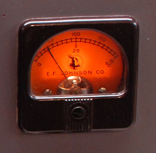
The Ranger meter can be confusing to read, and the instruction manual doesn't
help much. The table below shows the full scale value for each function and
what each division on the meter represents:
| Meter Function |
Full Scale |
Each Division |
| Oscillator | 40 mA | 2 mA |
| Buffer | 40 mA | 2 mA |
| Grid | 10 mA | 0.5 mA |
| Plate | 200 mA | 10 mA |
| Modulator | 200 mA | 10 mA |
Take a look at the picture below and then try to figure out what the reading
represents. The correct readings are shown below the picture.

| In the picture above, the correct reading would be: 37 mA on the top 0 - 200 mA Scale (Plate or Modulator Current) 1.9 mA on the middle 0 - 10 mA Scale (Grid Current) 7.6 Ma on the bottom 0 - 40 mA Scale (Oscillator or Buffer Current) |
Keep in mind that because of inaccuracy in the meter itself and in the multiplier resistors the readings may differ by as much as 5% or more from the actual value, so isn't necessary to read the current as close as I have above. In actual operation, the most important thing is to adjust the drive control so that the grid current is 2.5 mA and to be sure that the plate current is dipped to a minimum using the final control.
The table below is a list of the typical meter readings from my Viking Ranger:
| Band: |
Mode: |
VFO/Crystal Control: |
Frequency: |
Oscillator Current: |
Buffer Current |
Grid Current: |
Plate Current: |
Modulator Current: |
Power Output: |
| 160 m | CW | External VFO | 1830 kHz | 13.5 | 4 mA | 2.5 mA | 130 mA | 0 mA | 45 watts |
| 80 m | CW | Internal VFO | 3530 kHz | 23 mA | 5.5 mA | 2.5 mA | 135 mA | 0 mA | 45 watts |
| 80 m | CW | Crystal | 3530 kHz | 13.5 mA | 5.0 mA | 2.5 mA | 135 mA | 0 mA | 45 watts |
| 80 m | CW | External VFO | 3530 kHz | 15.5 mA | 5.0 mA | 2.5 mA | 135 mA | 0 mA | 45 watts |
| 40 m | CW | Crystal | 7029.5 kHz | 14 mA | 10 mA | 2.5 mA | 135 mA | 0 mA | 45 watts |
| 40 m | CW | External VFO | 7029.5 kHz | 14.5 mA | 10.5 mA | 2.5 mA | 135 mA | 0 mA | 45 watts |
The table below lists the settings of the front panel controls on my Viking
Ranger for a variety of frequencies. In each case the transmitter was operating
into a 50 ohm load:
| Band: |
Mode: |
Frequency: |
Buffer |
Final |
Auxiliary Coupling |
Coupling |
Power Output |
| 160 m | CW | 1830 kHz | 66 | 53 | 2 | 1.5 | 45 watts |
| 80 m | CW | 3530 kHz | 51 | 57 | 2 | 0 | 45 watts |
| 40 m | CW | 7029.5 kHz | 56 | 55 | 4 | 1.5 | 45 watts |
 Back to Dr. Greg Latta's
Electrical Engineering and Amateur Radio Pages
 If you have any questions or
comments, you can send E-Mail to Dr. Greg Latta at
glatta@frostburg.edu