Click on the image for a larger view.
Click here for a super detailed view.

| Johnson Viking Ranger - Main Page and Exterior Photos | Alignment |
| Interior Photos of the Transmitter | Modifications |
| Restoration | Schematic Diagrams and Circuit Descriptions |
| Typical Operating Conditions | Manuals and Advertisements |
Important Safety Note: Working on or testing equipment such as the Viking Ranger is extremely dangerous since very high voltages are present when the equipment is turned on, and may even be present when the equipment is turned off and unplugged. If at all possible, do all work with the equipment off and unplugged and be sure that the capacitors are properly discharged before working on the equipment. The operator assumes all risk and liability in such matters! Do not work on this type of equipment unless you are experienced with working around very high voltages!
Introduction:
The Johnson Viking Ranger is a beautiful example of the art of
"point-to-point" wiring. Wires run directly from one point to another
without any circuit boards. Some areas can get quite crowded, such as the power
entry and exit area, but careful parts placement prevents short circuits. When
a problem is encountered with point-to-point wiring one of the first things to
check for is a short circuit between components.
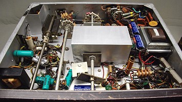
Below is a tour of the underside of the Ranger, starting with the microphone
and keying inputs and finishing with the modulator section. For newer hams who
have never been under the hood of a vintage transmitter, I think you will find
it quite interesting. To go to a specific area you can either click on the
table below or click on the appropriate region in the photo below the table.
Enjoy and 73,
Greg AA8V
Or
Click On Any Part Of The Picture
Below For Information On That Part Of The Transmitter

Click On Any Part Of The Picture Above For
Information On That Part Of The Transmitter
| Key and Microphone Inputs and Output Coupling Capacitors: These photos are two views of the microphone and key connectors and the output coupling capacitors. They were taken from opposite sides so that everything could be seen. The mic and key connectors are at the upper left in the top photo and the lower right in the bottom photo, inside the metal shield. The metal shield prevents any RF output from getting into the microphone or keying circuits. The RF output connector in the center at the top of the upper photo. To the right of it is an RCA connector that was added by me that connects to the microphone PTT (push-to-talk) line. At the right in the upper photo (left in the bottom photo) wires can be seen passing through the chassis that connect the band switch to the final tank coil on the top of the chassis. The large variable capacitor in the center of the photos is the output coupling capacitor C9, and the capacitors mounted on the rotary switch are the auxiliary coupling capacitors C40-C45. The variable capacitor and switched fixed capacitors are in parallel so that a large range of output capacitance is available. C9 has a maximum capacitance of 360 pf, and a total of 1600 pf can be switched in via the switch. This gives a total maximum capacitance of 1960 pf. This method of varying the capacitance is preferable to a single large variable capacitor in that it gives finer control of the output coupling, and saves a lot of space, since a 2000 pf variable capacitor would be quite large. The Johnson Ranger transmitter is the best I have ever seen when it comes to TVI shielding and filtering. The key jack and microphone input mounted inside the shield are carefully bypassed and filtered to prevent any harmonics from getting out. In addition to the usual bypass capacitor, a 4.7uH "firecracker" RF choke is in series with the key line for additional protection against TVI. |
 Click on the image for a larger view. Click here for a super detailed view. 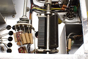 Click on the image for a larger view. Click here for a super detailed view. |
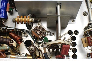
| Final Amplifier: The Johnson Ranger uses a single 6146 as the final amplifier tube. In this photo the 6146 tube socket can be seen near the middle of the photo. The band switch is below and to the right of the tube socket, and wires from the band switch can be seen passing through the chassis to the final tank coil on the top of the chassis. Notice that the tube socket and a solder lug on the right of the tube socket are riveted to the chassis. This is an indication that this Ranger was factory assembled and not a kit. Three wires run to the solder lug from pins 1, 4, and 6, the cathode of the tube. A triple connection to the cathode is one of the main features of the 6146 tube because it keeps inductance in the cathode connection to ground at a minimum and results in improved stability. The yellow/orange RF choke above and to the left of the tube socket is RFC7, the grid RF choke. This allows DC to pass to the grid of the tube, while blocking the flow of RF The AC line fuse is just barely visible at the bottom left of the photo. This was added when the line cord was replaced with a proper 3-prong grounding cord. Also at the bottom of the photo, just to the right of the fuse, mounted vertically on the chassis, is R15, the 30kohm screen dropping resistor. This resistor drops the voltage from the high B+ supply to the proper value needed by the 6146 screen grid. The metal shield at the top of the photo isolates the grid circuit of the final amplifier and prevents undesired feedback and oscillation. |
 Click on the image for a larger view. Click here for a super detailed view. |
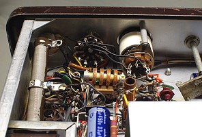
| Power Entry And Exit: The area of the chassis where the power cord and accessory connector are located is a well ordered mess and makes an excellent home for mice. When I first got the transmitter a mouse had moved in and the area was filled with sawdust and other mouse bedding. It took quite a bit of work cleaning it all out. The area is quite crowded because of all of the RF chokes and bypass capacitors that are used to suppress TVI. All lines in and out of the transmitter are filtered, not only with bypass capacitors directly at the entry/exit point, which is the usual case, but also with RF chokes. The accessory socket can be seen at the top center of the photo. The accessory socket carries DC power and filament power to accessories, and audio output from the internal modulator to a larger, higher powered, external modulator. For the filament connections, RF chokes made of heavy coiled magnet wire were used. One of these is discolored in the photo, probably from an accidental short in the filament line at some time in the past. For the other connections, which carry less current, 4.7uH "firecracker" RF chokes were used. None of these RF chokes have much reactance at HF, but they have enough reactance at VHF to help prevent the escape of VHF harmonics that can cause TVI. The power cord is at the top right in the photo. For the power cord, double section TVI filters were used, with two bypass capacitors and two RF chokes in each lead of the AC line. The final tank band switch can be seen at the left in the photo, and R15, the screen dropping resistor, and the AC line fuse can be seen between the band switch and the accessory connector. |
 Click on the image for a larger view. Click here for a super detailed view. |
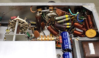
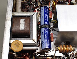
| Filter Capacitors and Power Supply Choke: Both the low B+ and high B+ supplies in the Ranger use choke input filters. This provides superior voltage regulation. LP1, the high B+ choke is on the top of the chassis, and LP2, the low B+ choke, is under the chassis and can be seen on the left side of this photo. The high B+ power supply used a single 10uf 700V filter capacitor (C77), and most of these capacitors have gone bad over the years. 700V capacitors are no longer available, so two 33uf/450V capacitors were placed in series, with 270k 3W equalizing resistors in parallel with each one. This gives an effective capacitance of 16.5uf at 900V, which is a big increase over the original 10uf at 700V. One of the 5000 pf (.005uf) bypass capacitors for the AC line can be seen at the lower left of the photo. The yellow/orange RF choke in the photo at the bottom right is RFC7, the final amplifier grid RF choke. |
 Click on the image for a larger view. Click here for a super detailed view. |
| Crystal Oscillator/VFO Buffer: Another very crowded area of the transmitter is the area around the crystal oscillator/buffer. This region also contains the socket for the 5R4 rectifier tube, which is just visible under the tap on the large power resistor on the left in the photo. The left side of the photo is dominated by R35, the 20kohm/20W power resistor that is used to adjust the screen voltage on the modulator tubes. This resistor is often burned out in older Ranger transmitters. It is also often damaged by hams who overtighten the tap on the resistor and damage the resistance wire, ruining the resistor. This resistor was completely absent when I got the transmitter. In its place was a jumble of fixed resistors that had been jury rigged into place. These were removed, and a proper resistor was purchased and installed. This resistor was the single most expensive replacement part I had to buy, costing $17.35. Proper operation of the modulator is only possible if the idle current through the 1614/6L6GC modulator tubes is the correct value. According to the manual, when the transmitter is properly loaded to 140mA of final amplifier plate current in phone mode (carrier output about 40W), R35 should be adjusted for an idle current of between 75mA and 90mA. Since R35 carries full high B+ voltage, extreme care must be used when adjusting this resistor. It must be adjusted only when the transmitter is turned off, unplugged, and the high voltage filter capacitor C77 has had a chance to discharge. You must also be sure to loosen the tap completely before trying to slide it, or your will damage the resistance wire and ruin the resistor. The drive control that controls the screen voltage on the buffer/multiplier can barely be seen in the dark area just above R35. This control was also burned out and had to be replaced. To the right of the R35, at the top of the photo, the Crystal/VFO switch and crystal socket can be seen. An external VFO input adapter made of cream colored CPVC pipe is plugged into the crystal socket and can be seen in the photo. This allows the signal from an external digital DDS VFO to be fed into the Ranger via the XT1 socket. The yellow/orange RF choke in the middle of the photo is RFC4, the crystal oscillator/buffer cathode RF choke, and the tube socket is just barely visible under the RF choke. Just to the right and in front of the choke, mounted vertically (with yellow wire), is the buffer/crystal oscillator tank coil, L5. This coil is adjusted for maximum final grid current on the 10m band, as shown in this link: How To Adjust L5. |
 Click on the image for a larger view. Click here for a super detailed view. |
| Crystal Socket and VFO Switch: The front center of the chassis is sparsely populated because the VFO band switch is located here. The VFO operates at a lowest frequency of 1750kHz on the 160m and 80m bands and on 7000kHz on all other bands. When the band switch is rotated from the 80m position to the 40m position, a pin on the shaft (at the center of the photo) engages a slotted plate on the VFO switch (square metal plate just above the shield at the bottom of the photo) and changes the position of the switch, changing the VFO from 1750kHz to 7000kHz. When the bandswitch is rotated from the 10m to the 11m position, a second pin engages the VFO switch, lowering the VFO frequency enough for operation in the 11m band. (This is why 11m comes after 10m on the band switch.) C78, the low B+ filter capacitor can be seen just behind the pins on the band switch shaft, and the speech amplifier (with large green capacitors) can be seen at the right. Just to the left of the pins on the bandswitch shaft RF chokes L2 (red) and L3 (brown) are visible. These are the VFO plate (L2) and cathode (L3) RF chokes. Below and to the left of the RF chokes, mounted vertically (with yellow wire), is the buffer/crystal oscillator tank coil, L5. The Crystal/VFO switch and crystal socket (with VFO input adapter installed) can also be seen in the photo at top left, and the yellow/orange RF choke at center left is RFC4, the crystal oscillator/buffer cathode RF choke. |
 Click on the image for a larger view. Click here for a super detailed view. |
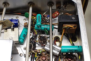
| Speech Amplifier: The Johnson Ranger was/is famous for its clean audio, which comes from a circuit utilizing a 12AX7 microphone preamplifier, a 12AU7 modulator driver, and a pair of 1614/6L6GC modulators. The 12AX7 tube socket is the upper 9-pin tube socket in the photo, and the 12AU7 tube socket is below it. The two 1614/6L6GC octal tube sockets are just visible at the bottom of the photo. The audio gain control is on the front panel at top right, and immediately below it is T3, the modulator driver transformer. The large green capacitors are C51, C55, and C71 (bottom right). The smaller green capacitor is C57. These were all tested and found to be in perfect condition. However, the two double section electrolytic capacitors in the speech amplifier (C50A & C50B and C59A & B) were all dried out and had no capacitance. These were replaced with four separate new capacitors having the same values as the original capacitors so the frequency response of the audio section would not be altered. The two silver capacitors between the modulator sockets at the bottom are C59A and C59B. The red "postage stamp" capacitor at top right is C52. When the Ranger was finished and testing on AM began, an intermittent problem was found with the speech amplifier. After a long, hard search the problem was traced to this capacitor. The capacitor was sometimes leaky, but the leakage resistance was so high (over 20Mohms) that it could not be measured with a standard ohmmeter. The leakage intermittently caused the second section of the 12AX7 preamplifier to saturate, which killed/distorted the audio. Replacing the capacitor cured the problem. The VFO switch and C78, the low B+ filter capacitor, can be seen in the photo on the left. Also visible in the photo is the 0.51ohm modulator current metering resistor. This is the green-brown-silver-gold resistor connected to the left octal socket at the bottom of the photo. |
 Click on the image for a larger view. Click here for a super detailed view. |
| Modulator and Clamp Tube: In this photo of the modulator section the two octal modulator tube sockets can be seen in the middle of the photo. The 9-pin socket for the 12AU7 modulator driver can be seen at top, and the 7-pin 6AQ5 clamp tube socket is visible at the lower right. The green-brown-silver-gold resistor connected to the left octal socket is the 0.51ohm modulator current metering resistor. The two silver capacitors between the modulator sockets are C59A and C59B, and the large green capacitor at right is C71. The large white capacitor mounted vertically at the lower right is C69, and the smaller white capacitor below the octal sockets is C60. The three 33kohm/1W resistors (orange-orange-orange-silver) wired in parallel at the lower right are R38A, R38B, and R38C. Together they form R38, an 11kohm/3W resistor that powers the screen grid of the 6AQ5A clamper tube. The clamper tube limits plate current in the 6146 final in the absence of excitation. |

Click on the image for a larger view. Click here for a super detailed view. |
 Back to Dr. Greg Latta's
Electrical Engineering and Amateur Radio Pages
 If you have any questions or
comments, you can send E-Mail to Dr. Greg Latta at
glatta@frostburg.edu