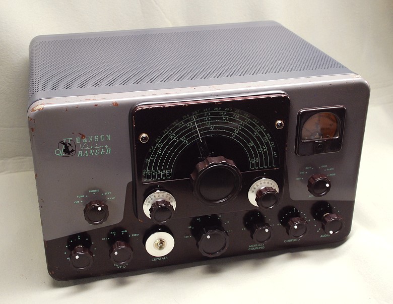
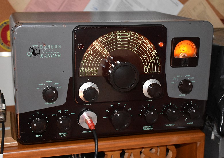
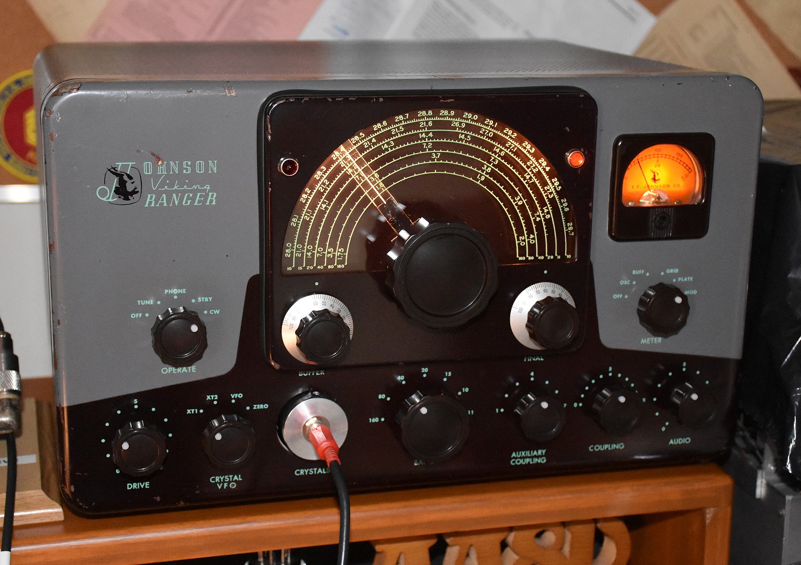
The Johnson Viking Ranger
by Greg Latta, AA8V
Restoration
Important Safety Note: Working on or testing equipment such as
the Viking Ranger is extremely dangerous since very high voltages are present
when the equipment is turned on, and may even be present when the equipment
is turned off and unplugged. If at all possible, do all work with the
equipment off and unpluggedand be sure that the capacitors are
properly discharged before working on the equipment. The operator assumes
all risk and liability in such matters! Do not work on this type of equipment
unless you are experienced with working around very high voltages!
Restoration:
Introduction:
On the evening of November 1st, 2013 I was on the 80m band with my 2E26/813
transmitter and I wound up working W3PH, Paul Heller, in Deep Creek Lake, MD.
During the QSO I mentioned to Paul that I did a lot of building with vacuum
tubes. Paul then mentioned that he had a Johnson Viking Ranger transmitter that
he was willing to give me for free if I wanted it. He had purchased it at a
hamfest some 30 years ago with the intention of restoring it, but had never
gotten to it. It had been sitting in a plastic bag in his shed all those years.
After a couple of e-mails Paul brought the Ranger to my house two days later,
and on November 3rd, 2013 I was the proud owner of a rather sorry looking
Viking Ranger. It was in terrible shape and full of sawdust and mouse
droppings, but the mice had simply moved in and hadn't eaten any of the rig.
With a lot of work it looked like it could be cleaned up and put back on the
air.
After six months of painstaking restoration work the transmitter went back on
the air Wednesday, June 11th, 2014. I made the first QSO with crystal control
and then switched to VFO control from my external digital VFO. I now have the
Ranger on the air on a regular basis. It sounds great, looks great, and was
well worth all of the time I spent working on it.
Links To Some Currently Available Parts For
The Johnson Ranger:
After I finished restoring my Ranger, I made a list a parts that I had
purchased during the restoration as well as parts suggested to me by others.
The result is the table below. At the time of writing (October 2021) the links
shown are valid, though they may obviously change with time, and parts
specifications may also change. Still, it is probably the most valuable
resource on this web page. I hope you find it useful.
Links To Some Currently Available Parts For
The Johnson Ranger
| Description |
Link |
Source |
| High B+ Electrolytic Capacitor C77 |
|
|
| 33uf 450V Electrolytic Capacitor - 2 Required |
598-336TTA450M
|
Mouser Electronics |
| 270k Ohm 3W Metal Film Resistor - 2 Required |
594-5093NW270K0J |
Mouser Electronics |
| Shunt each capacitor with a 270k resistor and place
the capacitors in series. Use in place of C77. |
|
|
| Low B+ Electrolytic Capacitor C78 |
|
|
| C78 - 47uf 450V Electrolytic Capacitor |
598-476TTA450MRZ
|
Mouser Electronics |
| Bias Supply Electrolytic Capacitors C90A and
C90B |
|
|
| C90A/C90B Replace with a single 30uf 150V
Electrolytic Capacitor |
75-TVA1412 |
Mouser Electronics |
| Speech Amplifier Electrolytic Capacitors C50A/B
and C59A/B |
|
|
| C50A/B Replace with two individual 10uF 50V
units |
598-106TTA050M
|
Mouser Electronics |
| C59A/B Replace with two individual 15uf 150V
units |
75-TE1508.1 |
Mouser Electronics |
| Drive Control R13: |
|
|
| R13 - Drive Control - 25k Ohm 5 Watt |
774-026TB32R253B1A1 |
Mouser Electronics |
| HV Power Resistor R35: |
|
|
| R35 - HV Bleeder and Voltage Divider - 20k Ohm 50W
Wirewound With Tap |
588-D50K20KE
|
Mouser Electronics |
| Mounting Brackets for R35 - Two Required |
588-9E
|
Mouser Electronics |
| Line Cord And Fuse: |
|
|
| 18-3 Line Cord - 2m (6 ft 7 in) |
562-311007-01 |
Mouser Electronics |
| Single Fuse Holder |
534-3536 |
Mouser Electronics |
| Pilot Lamps: |
|
|
| #51 Pilot Lamps |
560-51 |
Mouser Electronics |
| Speech Amplifier Modification: |
|
|
| 0.01uf/400V film capacitor - Replacement for C52 To
Increase Audio Bass Response |
75-MKT1813310404
|
Mouser Electronics |
| Front Panel Frequency Dial And Escutcheon
Seal: |
|
|
| Radio Daze Frequency Dial For the Viking Valiant and
Viking Ranger |
SKU:
DS-A691 |
Radio Daze |
| Rubber Seal For The Escutcheon - Universal U Channel
Rubber Seal Strip 1/32" Opening Edge Trim All Weather Protector Strip
(10ft) - |
Universal
U Channel Rubber Seal Strip |
WalMart |
| White Knob Pointers: |
|
|
| White Knob Pointers |
Deutsch
114017 Sealing Plug Bag of 10 |
Electrical Depot |
| VFO Input Modification: |
|
|
| 8-Pin Octal Plug - For VFO Input Modification |
P-SP8-500 |
Antique Electronic Supply |
| 6AX5 And 5R4 Rectifier Tube Replacement With
Diodes Modification: |
|
|
| Octal Tube Base - For 6AX5 And 5R4 Diode Replacement
Modification |
P-SP8-476 |
Antique Electronic Supply |
| 1N4007 1000V Diode - For 6AX5 And 5R4 Diode Replacement
Modification |
P-Q1N4007 |
Antique Electronic Supply |
| Modulator Tubes: |
|
|
| 6L6GC Modulator Tube - Pair |
Tung6L6STRMD
|
Sweetwater Sound |
Initial Cleaning:
As received the transmitter was very dirty and certain areas were full of mouse
droppings and sawdust. A thorough vacuuming with the shop vac and a chip brush
cleaned everything out. First inspection showed that the mice had simply moved
in and had not eaten anything. No frayed wires or other such damage was found,
and there was no corrosion on the chassis, just the usual dirt that would be
expected after almost 60 years.
Tube Testing:
The tubes were removed, making note of which particular socket each 6CL6 and
12AU7 was in. Noting the particular tube socket guarantees that each tube
goes back into the same socket, since alignment sometimes depends on the
particular tube, and there are two 6CL6 and 12AU7 tubes in the Ranger.
The tubes were tested in an Eico dynamic tube tester, and some were found to be
weak. These were replaced with tubes that I already had in stock. The 6AX5GT
rectifier showed some heater to cathode leakage, but it was high enough that it
would not cause any problems. The 6146 final amplifier tube tested OK, but the
only real way to test an RF amplifier tube is by actually using it, and that
would have to wait until later.
Testing The Power Transformer:
The power transformer is one part in a transmitter that is not easy to replace.
If the transformer is defective, then there is not much point in restoring the
transmitter, so testing the transformer was the first order of business after
testing the tubes.
The worst thing one can do is to plug in the transmitter and turn it on, hoping
for the best. This is a sure road to disaster. The transformer or filter
capacitors could be shorted, leading to at best a blown fuse and at worst a
fire. Instead, thorough checks should first be made with an ohmmeter to check
for shorts and other problems before the transmitter is even plugged in.
Filter capacitors should be checked for shorts, and also with a capacitor
tester if possible to see if they have the correct capacitance.
After thorough checks with an ohmmeter, all tubes were removed. In the case of
the Ranger, removing the rectifier tubes also disconnected the transformer
secondary from the rest of the B+ circuits, allowing me to independently check
the transformer and transformer primary circuit.
The transmitter was plugged into a VARIAC (variable AC source)
and a voltmeter was placed across the high voltage secondary. The VARIAC was
set for 10% (about 12V), and the transmitter was turned on. The voltage on the
high voltage secondary was observed to be 10% of the expected value. The other
secondaries were also checked, and all showed 10% of the expected value. The
VARIAC was slowly increased to 25%, 50%, 75% and finally 100% with checks on
the secondary voltages each time to confirm proper operation. No other problems
were observed. The transformer appeared to be OK.
Checking The Filament Circuits:
After the power transformer was tested, all tubes except the rectifier tubes
were plugged into their sockets and the transmitter was turned on. All of the
tube filaments should have lit up, but quite a few did not. After checking the
schematic and the manual it was found that unless the 9-pin accessory plug was
plugged in, some of the tubes were disconnected from the filament supply.
Inserting the accessory plug cured the problem and all of the tubes lit up,
confirming proper operation of the filament circuits.
Testing The B+ and Bias Circuits
To test the B+ and bias circuits, all of the tubes except the rectifiers (5R4,
6AX5, and 6AL5) were removed. The filter capacitors in the high B+ (C77)
low B+ (C78)
and bias (C90A and
C90B) circuits were tested with an ohmmeter and capacitor tester and found
to be OK. A jumble of resistors used to replace R35 was also removed. The line
voltage was then brought up slowly on the VARIAC while the output of these
supplies was tested. All seemed to produce full output when the VARIAC was
brought all the way up, and no overheating was observed anywhere in the
transmitter.
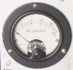
However, there was a problem in the the plate current meter indicated plate
current even though no other tubes were in the transmitter. This was initially
a concern, but it turns out that this is normal. The final amplifier/clamper
tube circuit is wired so that R15, the 30kohm screen dropping resistor, will
draw current through the plate current meter even when the clamper tube and
final tube are not installed. Thus, the power supplies, and all of the
power supply distribution circuits throughout the transmitter, were OK.
Some General Comments On Replacing
Electrolytic Capacitors:
Electrolytic capacitors contain an electrolyte that can dry out over the years.
They can still test and function fine if they contain only a fraction of the
electrolyte. When a vintage radio is first brought back on line the
electrolytic capacitors may function fine at first. However, after some use the
heat from the equipment may dry out what is left of the electrolyte and then
they fail.
In the long run, it is best to eventually replace all of the
electrolytic capacitors (called "recapping") in a piece of vintage
equipment. The needed capacitors can all be purchased and installed at the same
time. This saves shipping costs and avoids having to open up the equipment
multiple times.
To obtain a high enough voltage rating power supply capacitors may have to be
replaced with multiple identicle units in series with appropriate equalizing
resistors across each, as was done for C77. For
power supply capacitors a higher capacitance and/or voltage rating is OK, as
was done for C78.
For electrolytic capacitors in speech amplifiers and audio circuits, such as
C50A/B and C59A/B, the capacitance should not be changed, since this
could alter the frequency response. However, a higher voltage rating is OK.
"Can" capacitors and other units containing several capacitors are
very hard to find (or are very expensive) and can be replaced with individul
units. However, for can capacitors, disconnect the bad unit but leave
it in place for aesthetic purposes.
Ordering Replacement
Parts:
With the power supplies working properly, it sure looked like the Ranger would
ride again! There was still a long way to go though. The transmitter was
filthy, and there were still other parts that were obviously defective, such as
the drive
control, R13, which was burned out, and
R35,
the modulator screen dropping resistor, which was totally missing.
It turns out that parts such as these are still available, and they aren't that
expensive. However, shipping costs can be a substantial, and the way to
minimize shipping costs is to order all of the parts you will need or MIGHT
need at the SAME time. It is cheaper in the long run to order a part you
might need and not use it than to have to order it later, and pay
additional shipping costs. If the part isn't used, it just goes into your parts
stock for future use.
In addition to R13 and R35, I also wanted to replace all of the
electrolytic capacitors, including those in the power supplies. (The power
supply electrolytics, though not original, and still good, were at least 30
years old.) I also planned to replace any paper capacitors (such as those in
the audio section) with modern ones.
Using the parts list in the manual, I came up
with a list of parts that I would need. For electrolytics in the audio section,
I wanted to keep the values the same so that the audio response would not be
affected. For the power supply electrolytics, moderately larger capacitors
could be used. The high B+ filter capacitor C77 was a 10uf/700V unit. Such
capacitors are no longer available. Instead, two 33uf/450V units were placed in
series with 270kohm/3W film resistors across each one to equalize the voltage
to give the equivalent of a 16.5uf/900V filter capacitor. (Note: Never use
carbon resistors for equalizing resistors! Their negative temperature
coefficient makes them unstable.)
When shopping for parts, remember that larger power values for potentiometers
such as R13 (25kohm/4W) are perfectly acceptable. When the Ranger was made, 4W
potentiometers were standard. My favorite parts supplier,
Mouser Electronics, did have a 25kohm/4W
potentiometer available. The trouble was that it was special order only and
would cost $66!! It turns out that 5W potentiometers are now standard, and a
25kohm/5W unit was available for only $3.61!
For those who may need to replace R13, here is the part number that I used:
Mouser Part Number:
774-026TB32R253B1A1
For R35, which is a 20kohm/50W tapped wirewound power resistor I ordered the
following:
Mouser Part Number:
588-D50K20KE
You will also need two of the following mounting brackets for R35:
Mouser Part Number:
588-9E
Other parts that might be hard to find that I ordered from
Mouser Electronics included the following:
3 Conductor Line Cord:
Mouser Part Number:
562-311007-01
#51 Pilot Lamps:
Mouser Part Number:
560-51
Drive Control Replacement And Initial RF
Test:
With replacement parts on hand, the first thing I did was to replace
R13, the
drive control, which controls the screen voltage on the V4, the
6CL6
buffer/multiplier, and was the last part that needed replacement before I
could check the transmitter for actual RF output. Replacement was fairly
straightforward. Some of the wires to the control were quite short, but I was
just able to make them reach.
Once a new drive control was installed, I reinstalled all of the tubes, set the
band switch to 40m, and placed my Sangean portable shortwave receiver (in CW
mode) next to the transmitter. With the transmitter in tune up mode and the
meter switch set to read grid current, I keyed the transmitter and checked to
see if I could hear the VFO signal in the receiver. No signal was heard and no
grid current was observed, regardless of where I tuned the transmitter. This
meant that either the VFO wasn't working or that it was way out of alignment.
The VFO was going to need some work.
I switched to crystal control, and after inserting a 40m crystal into the
crystal socket I immediately heard the signal on my receiver and observed grid
current. The buffer control and drive controls worked just as they should, and
the signal was very clean and chirp free. I switched to 20m and 15m and still
had plenty of grid current. The crystal oscillator and buffer stages were
working fine.
After connecting a dummy load and Bird wattmeter to the output of the
transmitter, I switched to CW mode and tried tuning up the transmitter. I got
plenty of output and the final, auxiliary coupling, and coupling controls all
worked exactly as expected. Maximum output was about 50W, which was exactly
what it should be. The final amplifier tube and associated circuits all seemed
to be in great shape. The signal sounded clean and the keying was chirp free.
The Ranger was coming back to life!
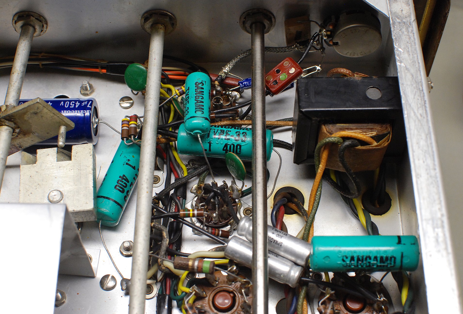
Power Supply Rebuilding And
Replacement Of R35:
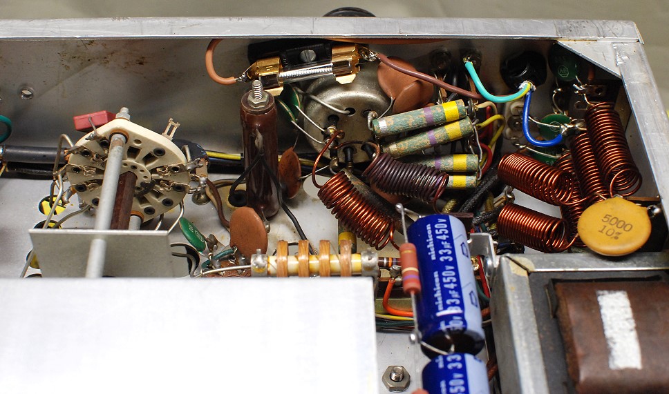
With the RF sections working (except for the VFO) I turned my attention to the
power supply filter capacitors
C77,
C78, C90A/B, and
R35,
the modulator screen dropping resistor.
Though
C77
and C78
had already been replaced and were fine, they were still 30 years old, and I
thought it best to replace them with modern units.
C77
was originally a 10uf/700V capacitor. This was replaced with two 33uf/450V
capacitors in series to give an equivalent capacitance of 16.5uf at 900V. Each
capacitor was shunted with a 270kohm/3W film type equalizing resistors as shown
in the photo below:
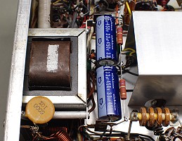
Two 33uf/450V capacitors shunted by 270kohm/3W
equalizing resistors were used to replace C77.
Click on the image for a larger view.
Click here for a super detailed
view.
C78
was originally a 30uf/450V capacitor. It was replaced with a 47uf/450V unit.
Capacitors
C90A
and C90B in the keyer/bias supply were originally a two section 15uf/50V
capacitor with both sections wired in parallel. This unit had dried out and was
replaced with a single 30uf/150V capacitor.
R35
was a bit of a problem because it was completely missing from the transmitter
and had been replaced with an arrangement of fixed resistors. I had already
removed these, but had no idea how R35 was supposed to be mounted. However, I
found a copy of the assembly manual on-line
and this showed where R35 should be mounted. I was amazed that, even after
almost 60 years, my replacement resistor was exactly the same size as the
original, and fit beautifully into the original mounting holes! You can see the
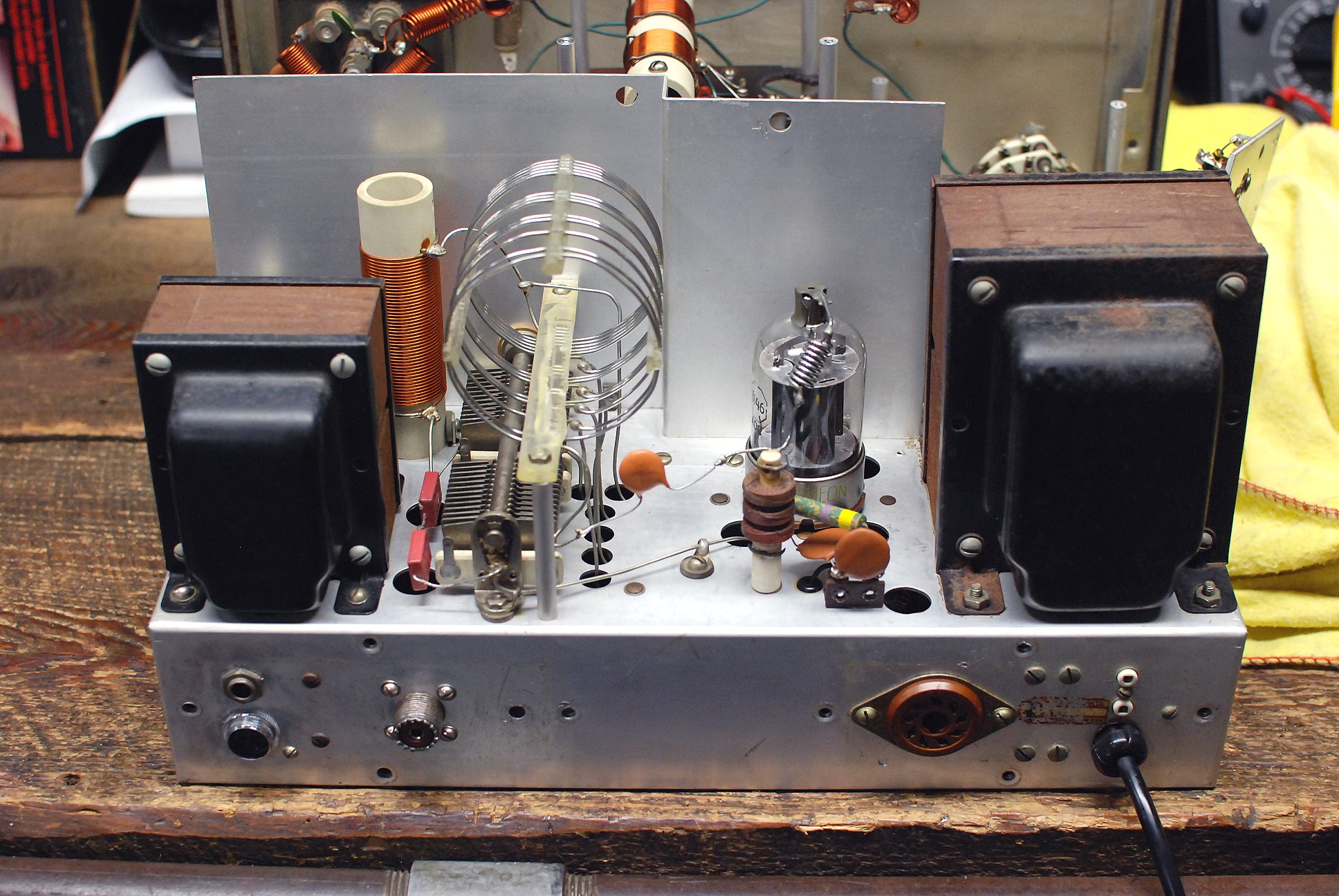
new resistor in the photo below:
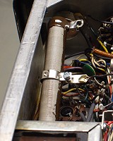
Resistor R35
Click here for details on
adjusting R35
The tap on the resistor was initially set about half way down. This would
give an initial screen voltage of about 250V maximum on the 6L6GC modulator
screen grids. Final adjustment would be made later.
Click here for details on
adjusting R35. Be sure that the tap is completely loosened when
adjusting it. Do NOT overtighten the tap. The tap only needs to be tight enough
to hold it in place. Overtightening or moving the
tap while not completely loosened will break the resistance wire and ruin the
resistor!
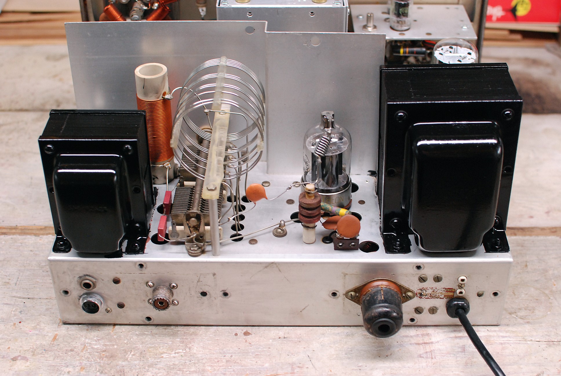
Line Cord And Fuse Holder
Installation:
The Ranger was made at a time when power cords were not grounded. The fuses
were placed in a special plug at the end of the line cord. Modern safety codes
dictate that a grounded 3 conductor line cord should be used on the Ranger. I
had cords in my junk box, but they were large and heavy. Since I was already
ordering other parts from Mouser
Electronics, I just added a new line cord to the order. The cord was 6'
7" long with 18/3 wire. The Mouser part number is below:
3 Conductor Line Cord:
Mouser Part Number:
562-311007-01
I had a large number of cord strain reliefs in stock and found one that would
fit the the cord and the hole in the Ranger. The cord went in easily, but
figuring out where to put the fuse was another matter. The back panel layout of
the Ranger didn't permit the use of a a standard single hole mount fuse holder.
Instead, I had to use a molded base fuse block. I had one in stock,but
Mouser Electronics has them with this
stock number:
Single fuse holder:
Mouser Part Number:
534-3536
This could be squeezed in right next to the accessory socket by drilling a
single hole through the panel. Be very careful when drilling the hole
not to damage anything! I used a 5A slow-blow fuse. See the photo below.
A molded base fuse holder can be squeezed in on the back panel as seen at top
center in this photo.
Click on the image for a larger view.
Click here for a super detailed
view.
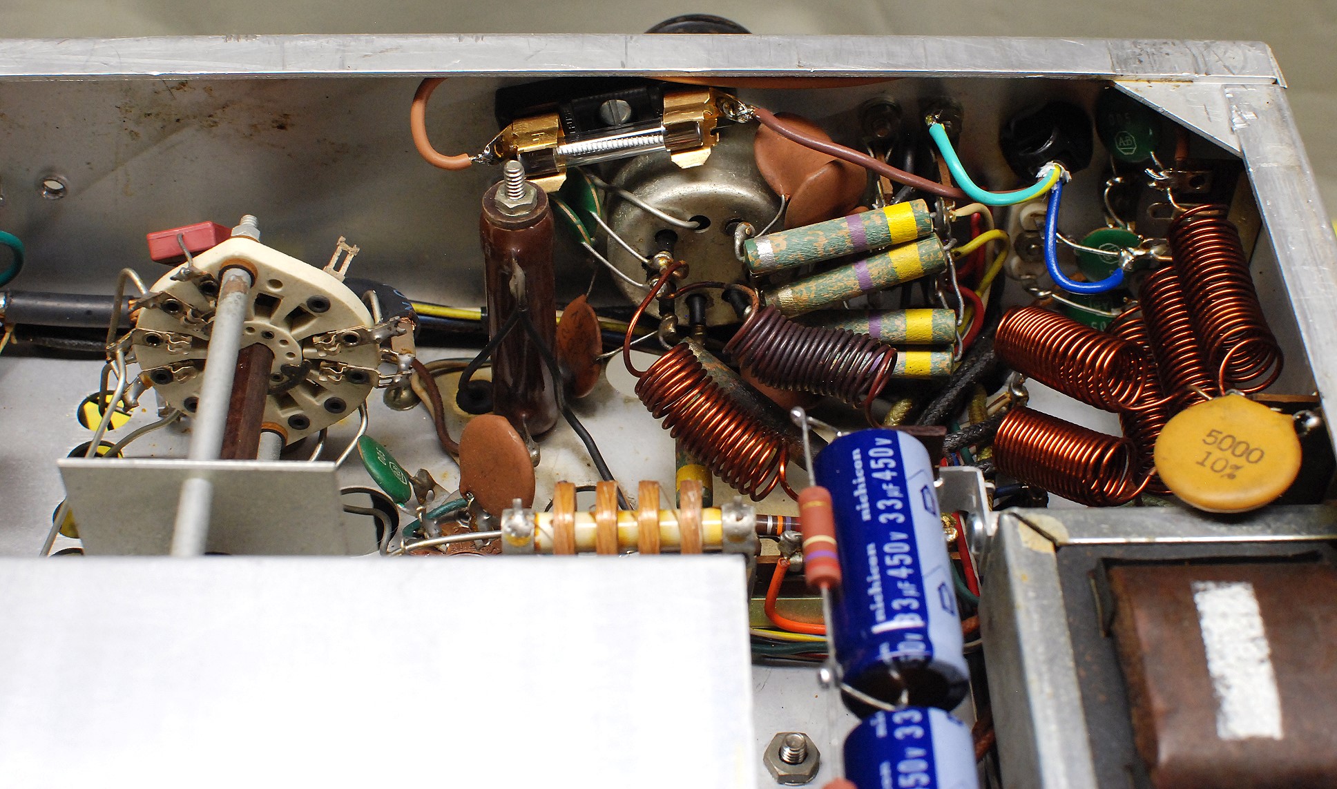
Speech Amplifier Capacitor
Replacement:
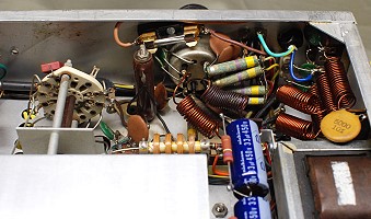
There are two double section electrolytic capacitors in the speech amplifier,
C50A/B and C59A/B. These had both dried out and had no capacitance. Though it
is OK to use larger capacitance in the power supply, using larger capacitances
in the audio section could alter the frequency response. C50A/B and
C59A/B were therefore replaced with new capacitors having the same
capacitance. C50A/B was replaced with two 10uf/50V units, and C59A/B was
replaced with two 15uf/150V units. (150V capacitors were used for C59A/B
because they were much cheaper.)
Speech Amplifier
Click on the image for a larger view.
Click here for a super detailed
view.
In the photo above, C50B is the blue capacitor just to the left of the red
postage stamp capacitor at top, and C50A is barely visible under the red
postance stamp capacitor. C59A and C59B are the silver capacitors near the
bottom of the photo, between the two octal tube sockets.
Though I had purchased replacement capacitors for the green paper capacitors
visible in the photo, these were tested with a capacitor tester and were and
found to be good. Since they were moulded in plastic, it was unlikely that they
had deteriorated, so they were left alone. The new capacitors I had purchased
went into my stock to be used elsewhere in the future.
Modulator Testing:
With all of the capacitors in the modulator in good shape, I installed Svetlana
6L6GC modulator
tubes, and decided to test the
modulator. I wanted
to measure its output at flat topping and also its frequency response. The
modulator drives the final amplifier through the modulation transformer, T2.
The output of this transformer is available at the accessory socket X13A on the
back of the transmitter. However, a suitable load must be connected to the
transformer for testing.
The modulator was tested without the 6146 final amplifier tube
installed, and thus without the final amplifier drawing any plate current. This
yields a higher plate voltage on the modulator tubes than during actual use,
but still can still provide meaningful results. The modulator must, however,
be tested with the key down, since this affects the bias on the modulator
tubes. As to R35, my initial adjustment was pretty near the mark, because it
gave a modulator resting current of 72mA during keydown conditions in phone
mode. This was very close to the 75mA minimum
specified by the instruction
manual so I did not, at this time, readjust R35.
The impedance that the modulator drives is the final amplifier plate voltage
divided by the final amplifier plate current. According to the transmitter
manual, the final amplifier should be loaded to 130mA of plate current in phone
mode. At that plate current, the plate voltage would be 500V and the modulator
impedance would be 500V / 0.13A=3850ohms. I had a collection of large 10W-35W
wirewound resistors in my shop, and wired several of these in series and in
parallel to produce a 3750ohm resistor, which is within 3% of the required
3850ohms.
The 3750ohm resistor was connected across the entire secondary of the
modulation transformer at X13A, the accessory socket, and an oscilloscope was
connected across the resistor. A 1kHz sine wave was then injected into the mic
input. The audio gain control was increased until clipping was observed on the
scope, which occurred at 430V RMS, corresponding to an output of
(430V)*430V)/3750ohm=49.3W. The output was reduced to 200V RMS (10.7W output)
and the frequency was varied above and below 1kHz to find the -6dB frequencies
where the output voltage dropped to 100V RMS, half of its value at 1kHz. The
frequencies where the output was 6dB lower than at 1kHz were found to be 110Hz
and 3500Hz.
To properly modulate the 6146 final, 65W/2=32.5W would be needed from the
modulator. Even under real operating conditions, with the final amplifier
operating and with lower plate voltage, the modulator could clearly meet that
requirement. The frequency response of the amplifier was also found to be very
good. Assuming a good microphone, the Ranger should sound great on the air!
VFO Repair And Cleaning:
Initial testing had shown that the VFO was not working, though no problems
could be seen when the lid to the VFO cabinet was removed. To access the rest
of the VFO, the VFO cabinet was carefully removed and two problems were
immediately found:
1. Mice had also moved into the VFO cabinet and the entire area was a mess.
2. The original VFO regulator dropping resistor
R3 had
burned out and had been replaced with a new resistor, one end of which was held
in place with an alligator clip! Evidently, whoever did the repair couldn't
reach that end of the resistor with a soldering iron, so they used an alligator
clip. Not exactly a stable repair, but you have to give them credit for
ingenuity!
The mouse bedding was cleaned out and the entire VFO area was thoroughly
cleaned. As elsewhere in the transmitter, the mice had only moved in, and had
not eaten any wires. The chassis and all components inside the VFO cage were
cleaned with Q-tips and lighter fluid (naptha) and then waxed with Q-tips and
Pledge furniture polish to prevent dust from adhering in the future.
Resistor R3
and the alligator clip were removed and replaced with a new 3W film resistor.
This wasn't easy, since things were very tight, even with the VFO cabinet
removed. (The original repairer probably didn't remove the VFO cabinet, which
would have made soldering one end of
R3
impossible. That's probably why they used the alligator clip.)
After replacing R3, the VFO
came to life. The frequency was not stable, and jumped around a bit. All
connections inside the VFO cabinet were resoldered, but the instability
remained. Most likely, the fixed capacitors had become unstable over the years,
and would have to be replaced to settle down the VFO. Since I planned to use an
external VFO anyway, I left the original capacitors in place, and reinstalled
the VFO cabinet.
Chassis Cleaning:
With most of the electrical restoration done, it was time to worry about the
cosmetic appearance of the Ranger. The chassis, front panel, knobs, and cabinet
were all in need of work, and I decided to tackle the chassis first.
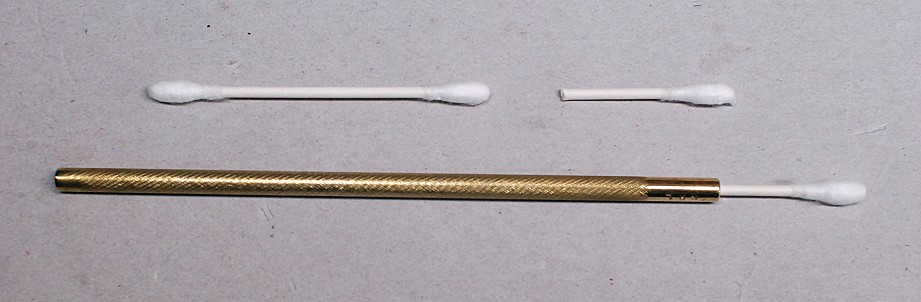
My standard procedure is to first clean as much of the chassis as possible with
a very small rag or piece of paper towel and Ronsonol lighter fluid (naptha).
Over the years I have found that lighter fluid is relatively benign and does a
great job of cutting through grease and other deep grime. (If you are in doubt
as to whether to use the lighter fluid on a surface, test a small inconspicuous
area first.) After as much as possible is done with the rag, I then switch to
using Q-tips and lighter fluid. I mount my Q-tips in a special brass handle
that I made to hold them, as shown in the photo below:
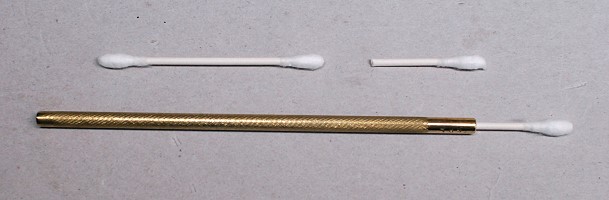
Brass Holder For Q-tips.
Click on the image for a larger view.
The handle is made of brass and has a hole drilled in one end that provides
a snug fit for the Q-tip. The Q-tips are cut off with a pair of side cutting
pliers and then inserted into the end of the handle, as shown in the photo. The
handle allows me to get into all of the tight places on the chassis that cannot
otherwise be reached. You can control the flex of the Q-tip by how much of the
shaft you leave on the Q-tip. I usually cut my Q-tips in half, and do a whole
bunch at once to save time.
To use the Q-tip, put some lighter fluid on it. If you get it too wet, touch it
to a small rag or piece of paper towel to remove the excess. When the Q-tip
gets dirty, take it out and insert another. You go through a lot of Q-tips, and
it is much like cleaning the floor of your kitchen with a toothbrush, but you
can get to all of those tight places and get them all clean.
I even clean the components (variable capacitors, especially the
steatite/ceramic insulation, fixed capacitors, resistors, and coils (after
carefully testing on a small part of the coil)) this way as well. Yep, the
process is time consuming, but it is about the only way to really get the
chassis clean.
After everything is cleaned with lighter fluid, the entire process is
repeated using Pledge furniture polish to resist dust build-up and give
everything a nice shine.
Finally, after the top of the chassis is done, the entire process is
repeated with the bottom side.
It takes a lot of time, but in the end it is worth it, as can be seen in the
photos.
Front Panel Cleaning
To clean the front panel, the knobs and the front bezel were removed. The panel
and bezel were then cleaned with a small damp paper tower pad covered with
clear coat auto polishing compound. This compound contains the finest abrasive
available, and is normally used to polish the clear top coat applied to
automobiles. It will polish and clean panels without affecting silk screened or
painted makings. Carefully polishing the front panel removed the patina on the
panel and made the silk screen markings stand out very nicely. It also gave the
front panel a glossy finish. After cleaning the panel with the clear coat
polishing compound, a damp pad with only water on it was used to remove all
traces of the compound, and then Pledge furniture polish was used to wax the
panel. Though the front panel has some nicks in it, these give it some
character, and were left untreated. The rest of the panel looks new, as can be
seen in the photo below:
Front Panel After Restoration
Click on the image for a larger view.
Click here for a super detailed
view.
Knob Cleaning And Indicator Insert
Replacement
The knobs were cleaned by first removing the set screws, and then the white
indicator inserts were removed from them with a pair of needle nose pliers.
(Many of these were already missing). The knobs were then scrubbed down with
water and a toothbrush soaked with Soft Scrub kitchen cleaner. The soft scrub
does an excellent job of removing years of patina from the knobs, and the
toothbrush gets into the nooks and crannies of the knobs leaving them very
clean. The knobs were then sprayed and polished with Pledge furniture polish,
which puts the shine back on the knobs.
New white indicator inserts were made from 1/4" white acetal plastic rod I
had on hand. The acetal was turned down to a diameter of exactly 1/8",
with a length slightly longer than necessary. The end of the insert was beveled
very slightly in the lathe. The beveled end was then inserted into the knob and
snipped off with side cutting pliers, which leave the cut end a little out of
round and oval shaped. The insert was then removed, turned around, and the out
of round cut end was pressed into the hole, the oval shape providing the
friction needed to keep the insert in place. Some extra inserts were also
made to keep in stock in case any were lost in the future. A restored knob is
shown in the photo below:
Restored Knob
Click on the image for a larger view.
Frequency Scale Restoration:
The front bezel was removed from the front of the transmitter and then the
plexiglass frequency scale was carefully removed from the bezel. The bezel was
treated the same as the front panel. It was cleaned and polished with clear
coat auto polishing compound and then waxed with Pledge furniture polish.
Though there were some nicks in the finish, these were left in place, since
they gave the bezel some character.
The transmitter frequency scale posed a real problem. Aside from the usual
scratches and gouges in the plexiglas, a semi-circle had been cut out of the
middle of the scale, leaving an ugly rough edge on the inside of the scale, and
some of the major frequency markings were covered with blotches of some sort of
clear glue (super-glue?) All of these problems can be seen in the left photo
below.
The real problem was how to remove the blotches of glue. I eventually found by
careful testing that if I rubbed the blotches with Q-tips dipped in lighter
fluid and then very carefully scraped them with my fingernail, I could slowly
wear away the the blotches, without scratching the plexiglas or harming the
silk screened markings on the scale. It took a while, but I was eventually able
to remove all of the markings. Both sides of the scale were then carefully
polished with with clear coat auto polishing compound and then waxed with
Pledge furniture polish. After the polishing and waxing the scale had most of
its original shine and contrast.
The inside edge of the scale, where the semi-circle had been cut out, was
cleaned and painted with flat black enamel. This kept light from leaking out of
the inner edge and made it almost invisible against the front panel. If you
didn't know it beforehand, you might not notice that the inner part of the
scale was missing. The final results can be seen in the photo below on the
right. Luck was really with me on this one!
Frequency Dial
Replacement:
As mentioned previously, when I first got my Ranger the inner semi-circle of
the clear plastic frequency dial was cut out. I painted the exposed edge flat
black to prevent light from escaping and producing glare. This made the damage
to the frequency dial hard to see, but I still longed to replace the dial with
a new one.
It was a couple of years later that I found out that a company called
Radio Daze makes replacement parts and
dials for many vintage receivers and transmitters. They make a replacement
frequency dial for the Johnson Viking Valiant that will also fit the Ranger.
Their part number is DS-A691 . Below is a direct link to that replacement part:
Radio
Daze Frequency Dial For the Viking Valiant and Viking Ranger SKU: DS-A691
I immediately ordered the replacement dial and in late January of 2018 I
installed the new dial. What a difference it made! The photo below shows the
Ranger with the new frequency dial installed. The Ranger truly is a beautiful
transmitter. Some say it was the best looking transmitter ever made!

Ranger With New Frequency Dial Installed
Click on the image for a larger view.
Click here for a super detailed
view.
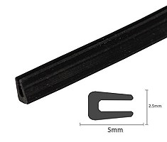
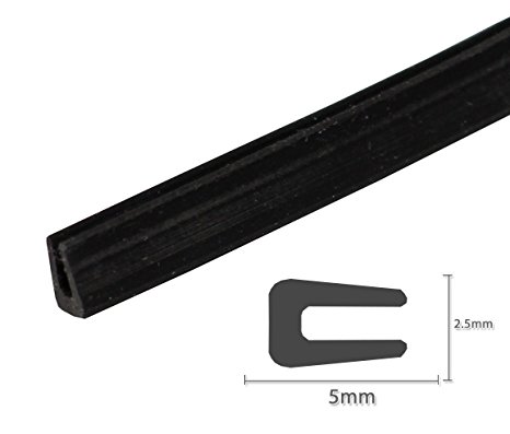
Rubber Seal For The Escutcheon:
On some Rangers the rubber seal behind the front escutcheon has rotted and
split. According to Steve Stroschein, W9XF, the following item, available from
WalMart.com, fits like a glove:
Universal
U Channel Rubber Seal Strip 1/32" Opening Edge Trim All Weather Protector
Strip (10ft)
Click here or on the image for a larger view.
Click
here to order from WalMart
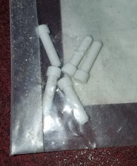
White Knob Pointers:
I used white acetal plastic to replace the white knob pointers on my Ranger.
However, Steve Stroschein, W9XF, found that an item available from Electrical
Depot, P/N 114017, called a "Sealing Plug" also works very well. A
bag of 10 sells for $1.55. Cut the plug to length, sand the cut edge, put a dab
of Super Glue on that edge with a toothpick & carefully slide it into the
hole in the knob. You can't tell the difference from the originals.
Deutsch
114017 Sealing Plug Bag of 10

Click here or on the image for a larger view..
Click
here to order from Electrical Depot
Transformer Airbrushing:
After the knobs, front panel, bezel, and chassis had been restored, the Ranger
was looking really great. Besides the cabinet, the only cosmetic problems left
were the high voltage power supply choke
LP1
(which looks like a large transformer) and power transformer
T1.
These were very rusty (especially the laminations), as can be seen in the photo
at left below. They had so many connecting wires (or the wiring was so tight)
that removing them from the chassis was not an option. I could perhaps
paint them with a brush, but that would leave brush marks, and there were areas
I could not get to with a brush. I finally decided that if I thoroughly masked
off the entire chassis I could airbrush the transformers. Airbrushing
would allow me to spray paint down into the nooks and crannies and get them
completely painted, without any brush marks.
As you can imagine, masking off every area of the chassis except for the
transformers was a big job. Masking off the area between
LP1
and
T1
(where the 6146 tube and tank coil are located) was particularly difficult. I
used newspaper and lots of Scotch blue masking tape. I had to cover the
components, but keep the masking away from the transformers so I could spray
their sides. It took several hours, but after the masking was finished I put
the chassis on a large lazy susan and airbrushed the transformers first with a
coat of Rustoleum Professional rusty metal primer (7569), and then with several
coats of gloss black Rustoleum (High Performance Protective Enamel V7579). The
airbrush allowed me to paint every surface of the transformers, even the sides
and backs. After letting the paint dry for a couple of days, I put all of the
tubes in the transmitter and turned it on standby, letting the heat gently bake
the paint. The results were worth all of the work, as you can see in the photo
at right below:
Cabinet Restoration:
As received the cabinet was in terrible shape. It had been spray painted with
some kind of dark blue paint that was chipping and flaking off, and there were
scratches all over the cabinet. It was apparent that a complete paint job was
needed.
Savogran Strypeeze paint stripper was applied to the cabinet and it was
stripped down to the bare metal. Steel wool was then used to remove the last
traces of paint and to thoroughly clean the base metal. The cabinet was then
washed and dried.
There was no hope of duplicating the original cabinet color (I wasn't even sure
what it was supposed to be!), so I decided to paint the cabinet a shade of grey
that matched the front panel. This was obtained by mixing 2 parts gloss black
Rustoleum (High Performance Protective Enamel V7579) to 1 part gloss white
Rustoleum (High Performance Protective Enamel V7592). The cabinet was first
airbrushed with a couple of coats of Rustoleum Professional rusty metal primer
(7569), and then airbrushed with several coats of the final grey. Some of the
rubber feet were missing from the cabinet. I went down to our local music/sound
equipment store and purchased a nice set of feet normally used for a large
guitar amplifier. These fit the cabinet perfectly. The final result was better
than I ever expected, as can be seen in the photos below:
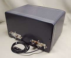
Cabinet After Restoration
Click on the image for a larger view.
Click here for a super detailed
view.
Final Speech Amplifier
Repair:
The transmitter went back on the air June 11th, 2014. I made several CW
contacts, first with crystal control, and then with my digital VFO. I used the
transmitter on CW for about a week and a half and got excellent signal
reports. Satisfied the RF circuits were working correctly, I decided to take
the plunge and operate on AM. However, after fitting a microphone to the
transmitter and testing it into a dummy load, I discovered I had intermittent
audio. I had a devil of a time tracking down the problem, because the
transmitter worked fine with the cabinet off, but would malfunction with the
cabinet on! Finally, after getting it to malfunction with the cabinet on, I
very carefully edged it out of the cabinet a little at a time until I could
very carefully insert a couple of test sockets into the speech amplifier tube
sockets. These allowed me to make voltage measurements from the top side
of the chassis. Measurements finally showed that
coupling
capacitor C52 (500pf) in the speech amplifier was leaking and causing the
second section of the 12AX7 preamplifier,V7B, to saturate. The leakage
resistance of C52 was so high (over 20Mohms) that it could not even be read on
an ohmmeter! Replacing the capacitor, however, cured the problem. I had my
first AM QSO with the Ranger on June 22nd, 2014. (My first AM QSO ever in 46
years as a ham!) Initial reports were that the audio sounded great. The Ranger
was riding the airwaves again!
 Back to Dr. Greg Latta's
Electrical Engineering and Amateur Radio Pages
Back to Dr. Greg Latta's
Electrical Engineering and Amateur Radio Pages
Questions, Comments, and E-Mail
 If you have any questions or
comments, you can send E-Mail to Dr. Greg Latta at
glatta@frostburg.edu
If you have any questions or
comments, you can send E-Mail to Dr. Greg Latta at
glatta@frostburg.edu
Thanks for stopping by!


