Click on any item in the photo for information on that item, or look in the list below.
<Previous Section |
Back to the The AA8V Station Page |
Next Section> |
| Section 4 (Left Side of Photo) | Section 4 (Middle Section of Photo) | Section 5 (Right Side of Photo) |
| Sections 4 and 5 Introduction | Wingfoot VFO Exciter Meters | Coaxial Antenna Relay |
| AA8V 6AG7 VFO Amplifier | Wingfoot 813 Amplifier Meters | Johnson Viking Ranger AM Transmitter |
| AA8V 6146B Linear Amplifier | Manual T/R Control for the Wingfoot VFO Exciter | PTT Relay System |
| AA8V Digital Keyed VFO | AA8V Automatic T/R System | Hallicrafters SX-96 Receiver |
| Wingfoot VFO Exciter Grid Box/VFO Control | ||
| Wingfoot VFO Exciter | ||
| Manual T/R Switch | ||
| Vibroplex Presentation Bug | ||
| Leather Desk Pad |
Introduction:
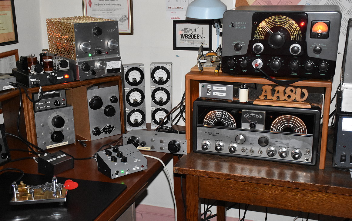
Section 4 (Left Side of Photo):
Except for the manual T/R switch on the desk, all
of the equipment in section 4 is homebrew. The upper shelf of this section
contains the AA8V digital VFO-6AG7 Amplifier-6146B
amplifier system. The VFO is just below the shelf on top of the
Wingfoot Exciter "Grid Box". On the desk under
the shelf is the Wingfoot VFO Exciter. The VFO tuning control or "Grid
Box" is on the left (under the digital VFO), and the main transmitter is
on the right. To the right of the shelf, on the desk, are the meters for the
Wingfoot Exciter and the Wingfoot 813 Amplifier meters.
Section 4 (Middle Section of Photo):
On the desk, in the middle of the photo, are the meters for the Wingfoot VFO
Exciter and Wingfoot 813 Amplifier. In front of the meters on the desk are the
remote mode control for the Wingfoot VFO
Exciter and an Automatic T/R System.
Section 5 (Right Side of Photo):
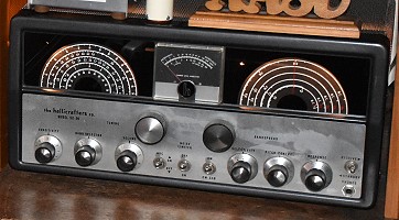
Section 5, on the right in the photo, contains a complete 1955 vintage AM
station consisting of a restored Johnson Viking Ranger AM transmitter and a
restored Hallicrafters SX-96 receiver, along with their associated accessories:
a push-to-talk (PTT) relay system and an antenna changeover relay.
| AA8V 6AG7 VFO Amplifier: The 6AG7 VFO amplifier is a class A RF power amplifier designed to take the signal from the AA8V digital VFO and raise it up to approximately 3W. It contains a built in power supply and operates on the 80m, 60m, 40m, 30m, and 20m bands. It can be used by itself with the digital VFO as a QRP transmitter, or it can be used to drive the AA8V 6146B linear amplifier. |
 |
| AA8V 6146B Linear Amplifier: The AA8V 6146B linear amplifier is a class AB2 linear RF amplifier. When driven by the 6AG7 amplifier and digital VFO it will produce an output of 50W on the 80m, 60m, 40m, 30m, and 20m bands. The amplifier has a built in power supply with regulated fixed bias and screen voltage (with screen grid protection) and has a single meter that can be switched to read the grid, screen, or plate current. |
 |
| AA8V Digital Keyed VFO: I designed a digital keyed VFO based on the N3ZI synthesizer board that I use with all of my crystal controlled transmitters, such as the Johnson Viking Ranger and my 6CL6 transmitter. I also use the VFO with my 6AG7/6146B transmitter system. An article on the VFO was published in the January 2014 issue of QST Magazine. The VFO has a resolution of 1Hz, an output of 5 volts peak-to-peak up to 7Mhz, and has useful output up to about 30MHz. It features a spotting switch, has 12 different memories, and can also be used as a signal generator. It is keyed via a keying amplifier that also simultaneously keys the transmitter. Keying the VFO keeps it off frequency during receive periods so it doesn't interfere with reception. |
 |
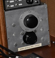
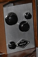
| Wingfoot VFO Exciter Grid Box/VFO Control: The Wingfoot VFO Exciter uses a Clapp oscillator circuit and has the oscillator LC tuned circuit on a separate chassis called the "Grid Box". The Grid Box is connected to the main transmitter chassis with two coaxial cables. This keeps the tuned circuit away from the heat produced by the exciter, and the result is a VFO with stability rivaling modern solid state transceivers. The Grid Box is built like a tank out of very thick aluminum and uses a very high quality coil, variable capacitor, and very high quality air trimmer capacitors. A National 5 to 1 reduction drive drives the variable capacitor. The VFO operates at 3500kHz on all bands except 30m, where it operates at 3367kHz. |
 |
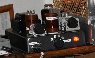
| Wingfoot VFO Exciter: The Wingfoot VFO Exciter is a remarkable transmitter built and designed by Jim Trutko, W8EXI, in the late 1950s with the help of the Goodyear Aerospace Corporation, where Jim worked. Jim passed the transmitter on to me when he retired and I restored it. It features an ultra stable VFO with stability comparable to modern transceivers. This is achieved by placing the frequency determining components on a separate chassis or "Grid Box" connected to the exciter by coaxial cables. The exciter uses timed sequence keying which gives it exceptional keying, and it operates on the 80m, 40m, 30m, and 20m amateur bands. The output is continuously adjustable from 3W to 27W via a variable screen voltage regulator circuit on the 2E26 final amplifier. The power supply for the exciter is a separate unit that rests on the floor. A separate remote mode switch is used to control the exciter. The "Wingfoot" name comes from the Wingfoot trademark that the Goodyear Tire and Rubber Company has used for years. |
 |
| Leather Desk Pad: I like to copy down everything on CW 100%, and I use a leather desk pad to provide a good, sound writing surface. Leather pads are expensive, but once you use one you will never go back to anything else. Large leather pads like the one in the photo can be obtained from The Elegant Office. |
 |
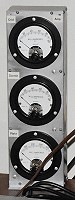
| Wingfoot VFO Exciter Meters: In most vintage transmitters a single switched meter is used to measure the final amplifier grid, screen, and plate currents. The Wingfoot VFO Exciter instead uses three separate Weston meters to simultaneously measure all three currents. Purchased new back in the 50s and 60s, Weston meters would have been very expensive (back in 1967 a single meter cost $14.40 or about $100 today!), but they were also available surplus at very reasonable prices, so using three meters wasn't quite as extravagant as it might seem. The top meter measures grid current (10mA full scale), the middle meter screen current (10mA full scale), and the bottom meter plate current (100mA) full scale. When the entire Wingfoot system is in use, all six meters kick up and down with keying, and are a wonder to behold. The entire operation of the system can be assessed with a single glance at the meters. |
 |
| Wingfoot 813 Amplifier Meters: In most vintage amplifiers a single switched meter is used to measure the final amplifier grid, screen, and plate currents. The Wingfoot 813 Amplifier instead uses three separate Weston meters to simultaneously measure all three currents. Purchased new back in the 50s and 60s, Weston meters would have been very expensive (back in 1967 a single meter cost $14.40 or about $100 today!), but they were also available surplus at very reasonable prices, so using three meters wasn't quite as extravagant as it might seem. The top meter measures grid current (100mA full scale), the middle meter screen current (100mA full scale), and the bottom meter plate current (500mA) full scale. When the entire Wingfoot system is in use, all six meters kick up and down with keying, and are a wonder to behold. The entire operation of the system can be assessed with a single glance at the meters. |
 |
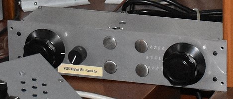
| Manual T/R Control for the Wingfoot VFO Exciter: The Wingfoot VFO Exciter uses a remote mode switch to control the exciter. Three modes are available: Operate, Standby, and Spot. In Standby mode only filament voltages are applied to the exciter. This keeps the system warmed up. Also, a 120V AC outlet on the Wingfoot exciter, used to switch a remote T/R coaxial relay, is turned off. In Spot mode, all stages operate except for the final amplifier. The120V AC outlet is also turned on. This places the entire system in transmit mode (except for the final amplifier) and allows the operator to key the transmitter and listen to the signal in the receiver, without putting a signal on the air. This is called "Spotting" the signal in the receiver. In Operate mode all stages are activated, including the final amplifier, and the 120V outlet is turned on, placing the entire system in transmit mode. The remote control is fitted with an internal relay that operates on 120V that can switch the mode remotely from Standby to Operate. A remote-remote control! When plugged into the Automatic T/R system, the Wingfoot VFO system can be automatically switched from Standby to Operate at the touch of the key. Spot mode must still be entered manually via the knob on the remote control. |
 |
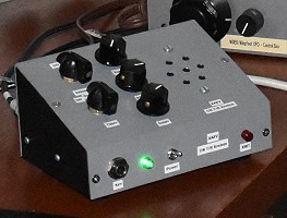
| AA8V Automatic T/R System: To make operation with my vintage receivers and transmitters as easy as with modern transceivers, I designed a solid state T/R system that places the station in transmit mode automatically when the key is pressed, and holds it in transmit mode for an adjustable time after sending ceases. I use this system with the 6x2 and SX-96 receivers, and the 6AG7/6146, Wingfoot VFO, and Johnson Viking Ranger transmitters. The key is plugged into the front of the unit, and then the unit is connected to the key jack of the transmitter. It can accommodate both negative and positive keyed transmitters. The back of the system has a normally off 120V AC outlet and a normally closed RCA jack. A Dow-Key 120V coaxial antenna relay is plugged into the 120V AC outlet, and the mute circuit of the vintage receiver is connected to the normally closed RCA jack. When the key is pressed, the 120V outlet is turned on, activating the T/R relay, and the normally closed circuit is opened, muting the receiver. A red light turns on indicating that the system is in transmit mode. An adjustable timer keeps the circuit in transmit mode for a short time after sending ceases. The T/R circuit can also be switched off if desired, or manually switched to transmit mode. Besides controlling the transmitter and T/R system, the key also keys a sidetone generator with adjustable pitch and volume controls. The sidetone can be turned off with a switch if desired. |
 |
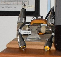
| Coaxial Antenna Relay: A coaxial antenna relay is used with the Johnson Viking Ranger and Hallicrafters SX-96 receiver as part of a push-to-talk (PTT) system. When the PTT on the microphone is pressed, the PTT system activates the antenna relay, switching the antenna from the receiver to the transmitter. The relay can also be used in CW mode with the automatic T/R system. In this mode, the 6x2 receiver or the Jupiter receiver can be used with either the Johnson Ranger transmitter or the 6AG7/6146B transmitter system for fully automatic transmit/receive switching. |
 |
| Johnson Viking Ranger AM Transmitter: In the middle and late 50s thee most coveted transmitter for any ham running AM was the Johnson Viking Ranger. It was the transmitter to have if you were running AM. With the ability to run on 160m - 10m, it featured a built in VFO and high level plate modulation with a powerful, great sounding modulator. With a handsome front panel and the ability to meter five different circuits the Viking Ranger set the standard for AM operation. The Ranger wasn't cheap. In 1955, a factory assembled Ranger cost $293, the equivalent of over $2500 in 2015! This particular Ranger was factory assembled, and it is fully restored. However, even after restoration the internal VFO is not as stable as I would like. Rather than use the internal VFO, I use my digital VFO and feed the VFO signal in through the crystal socket. The digital VFO works beautifully with the Ranger, and gives me absolute stability and digital frequency readout. |
 |
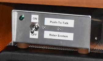
| PTT Relay System: When running AM, I prefer to use a push-to-talk (PTT) relay system. Rather than modify the Ranger, I simply feed the PTT line from the microphone to this external PTT relay system. On the back panel the relay system has a 120V AC outlet that is normally off, along with a normally closed RCA jack and a normally open 1/4" keying jack. A coaxial antenna relay is plugged into the 120V outlet, the receiver mute circuit is connected to the normally closed RCA jack, and the transmitter key is connected to the 1/4" key jack. When the PTT switch on the microphone is closed, the system turns on the 120V outlet activating the antenna relay, opens the normally closed RCA jack, muting the receiver, and closes the key jack, keying the transmitter. |
 |
 Back to Dr. Greg Latta's
Electrical Engineering and Amateur Radio Pages
Back to Dr. Greg Latta's
Electrical Engineering and Amateur Radio Pages
 If you have any questions or
comments, you can send E-Mail to Dr. Greg Latta at
glatta@frostburg.edu
If you have any questions or
comments, you can send E-Mail to Dr. Greg Latta at
glatta@frostburg.edu