| Main Power Supply Schematic Page | |
| Plate and Plate/Screen Supply | Bias Supply |
| Transformer T1 Primary Wiring | Inrush Delay Circuit |
| Power Connector Wiring | |
| Rectifier Diode | Relay |
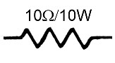
| Filter Capacitor | Inrush Limiting Resistor |
| Relay Dropping Resistor | Fuse |
Circuit Description:
When the power supply is first turned on, the surge of current that charges the
filter capacitors can damage the rectifier diodes. To limit the surge, a
10W limiting resistor
is inserted in the the primary of transformer T1. This limits the maximum
inrush current in the primary of T1 to about 12A. With the input power to T1
limited to 120V x 12A=1440W, the current in the 1500V secondary is limited to
1440W/ 1500V=0.96A. This is far below the maximum surge current rating of the
diodes, so the diodes are well protected. After a short time of roughly 0.05s
the limiting resistor is bypassed by the
relay, placing full line voltage on the primary of T1. A
fuse protects the limiting
resistor in the unlikely event that the relay fails to close and bypass the
resistor.
| Filter Capacitor: The filter capacitor is charged by direct current passing through the rectifier. The relay cannot pull in until the voltage in the filter capacitor is high enough, and this causes the needed delay between the initial turn on of the power supply and and the closing of the relay, which bypasses the inrush limiting resistor. |
 |
| Relay: The relay used in this circuit is the same as the relay that is used in several Ameritron amplifiers, including the AL-572 amplifier. It is Ameritron part number 408-6148. The relay is a SPST unit with contacts rated at 10A AC and a coil rated at 12V DC. The coil resistance is 127 ohms. The relay is used to bypass the inrush limiting resistor after the voltage on the relay coil becomes high enough. Until the voltage becomes high enough and relay pulls in, current in the primary of T1 must flow through the inrush limiting resistor, which limits the current in the transformer primary, and thus the secondary. It is the delay in the activation of the relay that gives the filter capacitors in the plate power supply time to charge up, and prevents the current surge in the rectifier diodes. In this power supply, it takes about 1/20s=0.05s for the relay to turn on, which is more than enough to protect the diodes. |
 |
| Inrush Protection Fuse: We have already shown that in the unlikely event that the relay fails to close, the inrush limiting resistor could handle the idle current requirement of the plate power supply, which is about 1A. It could also handle the initial turn on surge of up to 12A. However, if power supply is used above idle while the resistor is still in the circuit, the average current would be larger than the maximum of 1A and the resistor would overheat and eventually burn out. Before burnout, the power supply would not operate properly, since the voltage on the primary of T1 would be greatly reduced. This might not be noticed by the operator. To avoid a burnout situation and alert the operator to a problem, a 1A fuse is placed in series with the inrush limiting resistor. The fuse can easily handle the high inrush current, since it is very brief, and it can also handle the power supply idle current, should the relay fail to close. However, if the relay fails to close and the operator attempts to use the power supply above idle, the 1A fuse will blow, completely disabling the plate power supply, which would definitely be noticed by the operator. |
 |
 Back to Dr. Greg Latta's
Electrical Engineering and Amateur Radio Pages
Back to Dr. Greg Latta's
Electrical Engineering and Amateur Radio Pages
 If you have any questions or
comments, you can send E-Mail to Dr. Greg Latta at
glatta@frostburg.edu
If you have any questions or
comments, you can send E-Mail to Dr. Greg Latta at
glatta@frostburg.edu