The AA8V Wingfoot 813 Amplifier
High Technology Of The 1950s In The 2000s
by Greg Latta, AA8V
Transformer T1 Primary Circuit Description and Schematic Diagram
A Comment on Phase Notation:
In many cases "polarity", or more properly, "phasing"
does matter when connecting transformer primaries and secondaries, just
as it does when connecting batteries. However, because transformers operate on
AC, we cannot talk about "positive" or "negative"
connections to a particular primary or secondary. Instead, we label the
connections based on the instantaneous polarity of a particular
connection. Those connections that are is phase with each other
(simultaneously positive or negative) are marked with a black phasing
dot, as shown in the diagram below:

Transformer T1 Primary Phasing Diagram
Note that the black, blue, and orange leads above are marked
with a black phasing dot. This means that if, at a particular point in time,
the black lead is positive with respect to the brown, then, at that same point
in time, the blue is positive with respect to the grey and the orange is
positive with respect to the yellow.
Primary Wiring to Transformer
T1:
Transformer T1 has two 120V primary windings. The two primary windings can be
placed in parallel (OPERate) or series
(TUNE) by mode switch S2. When placed in series the output of T1 is
essentially cut in half.
Transformer T1 also has a primary buck/boost winding that can be connected in
phase (LOW) or out of phase (HI) with
the two major primary windings by HI/LOW switch S1. This gives a total of four
possible output voltages from the secondaries of T1.
Switch S1 (HV HI/LOW) determines whether the buck/boost winding is connected in
phase (buck) or out of phase (boost). When switch S1 is in the HI position, the winding is connected out of phase,
effectively lessening the number of turns on the primary and raising the output
voltage. When switch S1 is in the LOW position, the winding
is connected in phase effectively increasing the number of turns on the primary
and lowering the output voltage.
Switch S2 (OPER/TUNE) places the transformer primaries either in parallel or
series. When placed in parallel (OPERate Mode), full
output is obtained from the power supply. When placed in series (TUNE Mode), the output of the power supply is greatly
reduced. This greatly reduces the plate dissipation of the 813 while the
amplifier is being tuned up.
|
 |
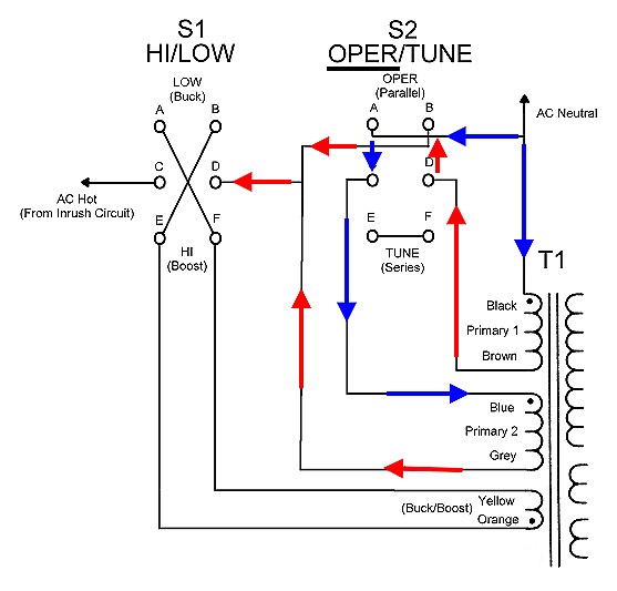
OPERate Mode - Primary Current
Flow:
OPER/TUNE in OPER)
For normal operation, switch S2 is placed in the OPERate position. This places
the 120V transformer primaries in parallel.
If you follow the arrows in the figure at right, you will see that for each
transformer primary current flows from the AC neutral connection (BLUE),
through the primary winding, and back to the AC Hot connection (RED) via the
HI/LOW switch and the buck/boost winding. Each transformer primary is thus
connected to 120 volts, and the transformer primaries are in parallel. This
yields full output from the power supply.
|
 |
TUNE Mode - Primary Current Flow:
OPER/TUNE in TUNE)
For tune up operation, switch S2 is placed in the TUNE position. This places
the transformer primaries in series.
If you follow the blue arrows in the figure at right, you will see that the AC
current flows from the AC neutral (BLUE) connection, through the first primary,
through S2 to the next primary (GREEN), and then back from the second primary
to the AC Hot connection (RED) via the HI/LOW switch and the buck/boost
winding. The two 120V primaries are thus in series and in phase.
By placing the primaries in series, the voltage applied to each primary is cut
in half from 120 volts to 60 volts. This cuts the secondary voltages in half
and cuts the output of the plate supply in half.
TUNE mode doesn't cut the total output of the power supply in half
because the screen supply (using T3) is not affected by the position of
S2. In fact, S2 has a center off position, where the plate supply can be
completely turned off. In that case the total power supply output is reduced to
about 450 volts.
|
 |
HI (Boost) Mode - Primary Current
Flow:
( HI/LOW in HI)
In normal operation switch S1 is set to HI (boost) to place the buck/boost
winding out of phase with the 120V primaries, effectively reducing the number
of turns on the primary and raising the output voltage.
If you follow the green arrows in the figure at right you will see that the
current flows from the Grey connection of Primary 2 through the HI/LOW switch
to the yellow lead of the buck/boost winding. The Primary 2 winding and the
buck/boost winding are thus connected out of phase. (Whether S2 is set
to OPERate or TUNE does not affect this connection.) The Buck/Boost winding is
thus connected out of phase overall with Primary 1 and Primary 2, effectively
decreasing the number of turns on the primary, raising the output
voltage.
|
 |
LOW Mode - Primary Current Flow:
( HI/LOW in LOW)
If lower plate voltage is desired, S1 can be set to LOW (buck) to place the
buck/boost winding in phase with the 120V primaries, effectively
increasing the number of turns on the primary and lowering the output voltage.
If you follow the green arrows in the figure at right you will see that the
current flows from the Grey connection of Primary 2 through the HI/LOW switch
to the orange lead of the buck/boost winding. The Primary 2 winding and the
buck/boost winding are thus connected in phase. (Whether S2 is set to
OPERate or TUNE does not affect this connection.) The Buck/Boost winding is
thus connected in phase overall with Primary 1 and Primary 2, effectively
increasing the number of turns on the primary, lowering the output
voltage.
|
 |
 Back to Dr. Greg Latta's
Electrical Engineering and Amateur Radio Pages
Back to Dr. Greg Latta's
Electrical Engineering and Amateur Radio Pages
Questions, Comments, and E-Mail
 If you have any questions or
comments, you can send E-Mail to Dr. Greg Latta at
glatta@frostburg.edu
If you have any questions or
comments, you can send E-Mail to Dr. Greg Latta at
glatta@frostburg.edu
Thanks for stopping by!