The AA8V Wingfoot 813 Amplifier
High Technology Of The 1950s In The 2000s
by Greg Latta, AA8V
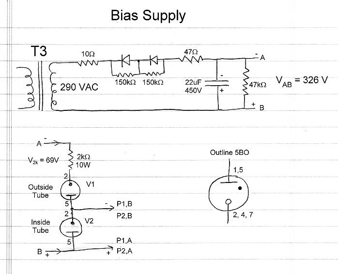
Bias Supply Circuit Description and Schematic Diagram
Click On A Section of the Schematic Below for Information on
That Part of the Circuit:
Circuit Design Considerations:
The bias supply provides operating and cutoff bias for the
813 tube. Little current (less than 30 mA at -150
volts DC) is required, but the bias should be regulated for best linearity. Two
voltage regulator tubes are used, giving the operator a choice of maximum bias.
One tube is an 0B2 and the other is an 0A2. Maximum bias is determined by the
tube mounted at V2. If the 0B2 is mounted at V2, the maximum bias is 108 volts.
If the 0A2 is mounted at V2, the maximum bias is 150 volts. Currently, the 0B2
is mounted at V2.
Transformer T3:
The bias supply is powered by a 290 V secondary on transformer T3. T3 also has
a 6.3 V secondary which runs the pilot lamp and a higher voltage,
centered tapped secondary which powers the
plate/screen supply.
|
 |
Surge Resistors:
Early solid state rectifiers did not have high surge ratings and could be
damaged by the turn-on surge that occurs as the filter capacitor first charges
up. To limit the surge current to a safe value, extra 10 ohm and 47 ohm
resistors were placed in series with the rectifier diodes.
In reality, these resistors are not really needed, since the transformer
secondary provides enough resistance to limit the turn on surge to a safe
value. Since they were already in the circuit, and they do no harm, they were
left in place.
|
 |
Rectifier Diodes:
To obtain a rectifier with a big enough peak inverse voltage (PIV) rating two
diodes are used in series. To keep the reverse voltage evenly divided between
the diodes, a 150k ohm equalizing resistors is placed across each diode. The
diodes used in the bias supply are the original "top hat" style
diodes.
|
 |
Filter Capacitor:
The output from the rectifier is a stream of pulses that need to be smoothed
out. The filter capacitor smooths out the pulses so that a steady DC voltage is
obtained.
Another way to look at it is that the rectifier output is a DC waveform with an
AC waveform superimposed. The capacitor short circuits the AC component to
ground, leaving only the steady DC component.
|
 |
Bleeder Resistor:
The filter capacitor can store a charge for a very long time, even after the
supply has been shut off and unplugged. To drain off the charge and prevent
possible shock, a 47k ohm "bleeder" resistor is connected across the
capacitor.
|
 |
Voltage Regulator Tubes:
Voltage regulator tubes have the property that the voltage across the tube is
constant provided the current is within a relatively wide range. For the OB2
and 0A2, the current must be between about 5 mA and 35 mA.
Tubes may be placed in series to give a higher voltage rating as is done here.
The OB2 operates at 108 V and the 0A2 at 150 V. Thus, the two in series operate
at 258 V.
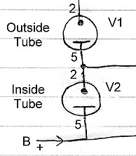
In the 813 amplifier it was eventually
found that very little bias was needed, so the output is actually taken from
across V2. In this case, V1 is really just used as a fancy dropping resistor,
and could be replaced with a resistor. However, since the tube and socket were
already in place, things were left as is.
Maximum bias is determined by the tube plugged into V2. It was eventually
determined that 108 V was more than enough to cut off the 813, so an 0B2 is
used at V2, and an 0A2 at V1.
|
 |
VR Dropping Resistor:
To keep the current through the VR tubes at the proper value, a dropping
resistor is placed in series with them. For intermittent loads, the resistor is
selected to allow the maximum current of 35 mA to flow through the tubes when
they are unloaded. A larger value can also be used, provided the tubes never
extinguish when they are loaded.
|
 |
VR Base Diagram:
The base diagram for the voltage regulator tubes is shown at right. There are
multiple connections to the cathode and plate, which allow the tube itself to
perform in some sense as a switch. For instance, it is possible to make
connections such that the output of the supply is disconnected if one of the VR
tubes is removed from its socket. |
 |
 Back to Dr. Greg Latta's
Electrical Engineering and Amateur Radio Pages
Back to Dr. Greg Latta's
Electrical Engineering and Amateur Radio Pages
Questions, Comments, and E-Mail
 If you have any questions or
comments, you can send E-Mail to Dr. Greg Latta at
glatta@frostburg.edu
If you have any questions or
comments, you can send E-Mail to Dr. Greg Latta at
glatta@frostburg.edu
Thanks for stopping by!