| Main Power Supply Schematic Page | |
| Plate and Plate/Screen Supply | Bias Supply |
| Transformer T1 Primary Wiring | Inrush Delay Circuit |
| Power Connector Wiring | |
| T1 Primary | T3 Primary |
| T1 High Voltage Secondary | Full Wave Center Tapped Rectifier |
| Bridge Rectifier | Choke Input Filter |
| Capacitor Input Filter | T3 Bias Secondary |
| T1 Current Inrush Secondary | High Voltage Fuse |
| T1 Filament Secondary | Pilot Lamp |
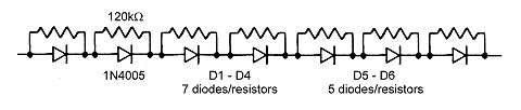
| Diode Strings |
Circuit Design Considerations:
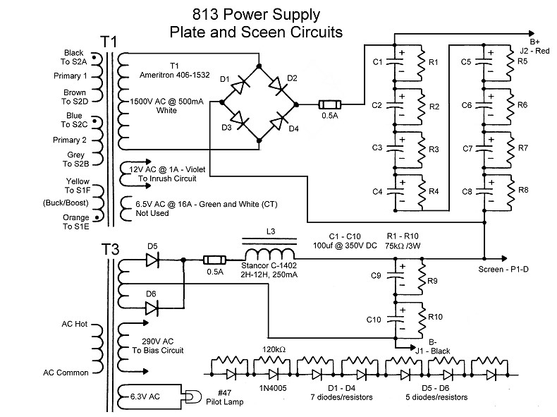
The plate and plate/screen supply provide the plate and screen voltages needed
by the 813 tube. Nominal plate voltage at 200W output
from the 813 amplifier is 2300 volts at 150 mA and screen voltage, if used, is
nominally 400 volts at 45 mA. This power supply is unusual in that a 400 volt
plate/screen power supply is run in series with another, 1900V high voltage
supply, the "plate" supply, to obtain the final 2300 volt plate
potential. The 400 volt supply also provides the screen voltage (if used) for
the tube.
| T1 Primary: T1 is an Ameritron stock number 406-1532 transformer. It is normally used in the popular Ameritron AL-811 and AL-811H amplifiers. Transformer T1 has two 120V primary windings and a buck/boost winding. The two primary windings can be placed in parallel (OPERate) or series (TUNE) by mode switch S2. When placed in series the output of T1 is essentially cut in half. The buck/boost winding can be connected in phase (LOW) or out of phase (HI) by HI/LOW switch S1. This gives a total of four possible output voltages from the secondary of T1. For a detailed description of how this switching arrangement works go to the Transformer Primary Circuit Description and Schematic Page. |
 |
| T1 High Voltage Secondary:
The high voltage secondary of T1 is rated at 500mA at a nominal voltage of 1500V. However, the actual voltage sepends on how the primaries are wired, as explained on the Transformer Primary Circuit Description and Schematic Page. |
 |
| Bridge Rectifier: A conventional full wave, bridge rectifier is used at the output of T1. The output of the diodes is fed through a 1/2 Ampere fuse to a capacitor input filter. Each of the diodes D1 through D4 is actually a string of diodes in series. |
 |
| Full Wave Center Tap
Rectifier: A conventional full wave, center-tapped circuit, powered by a center tapped secondary on T3, is used for the plate/screen supply. The negative output is the transformer center tap. The output of the diodes is fed through a 1/2 Ampere fuse to a choke input filter. Each of the diodes shown is actually a string of diodes in series. |
 |
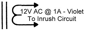
| T1 Current Inrush Secondary:
Besides the high voltage secondary, T1 also has a secondary rated at 12V at 1 Ampere. This is used to provide power for the current inrush circuit. |
 |
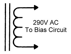
| T3 Bias Secondary: The bias power supply is powered by a 290 volt secondary winding on T3. Other secondary windings on T3 power the pilot lamp and the plate/screen supply. |
 |
| Pilot Lamp: A #47 pilot lamp is used on the power supply, powered by a 6.3 volt secondary on T3. |
 |
 Back to Dr. Greg Latta's
Electrical Engineering and Amateur Radio Pages
Back to Dr. Greg Latta's
Electrical Engineering and Amateur Radio Pages
 If you have any questions or
comments, you can send E-Mail to Dr. Greg Latta at
glatta@frostburg.edu
If you have any questions or
comments, you can send E-Mail to Dr. Greg Latta at
glatta@frostburg.edu