| Main Power Supply Schematic Page | |
| Plate and Plate/Screen Supply | Bias Supply |
| Transformer T1 Primary Wiring | Inrush Delay Circuit |
| Power Connector Wiring | |
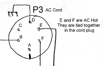
| AC Power Connector | Fuse Holders |
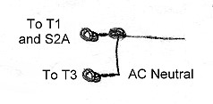
| AC Neutral Connections | High Voltage Output |
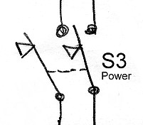
| Power Switch | Screen and Bias Output Connectors |
| Fuse |
Circuit Design Considerations:
The power connectors connect the power supply to the
813 amplifier and the AC power. The high
voltage connectors are James Millen type 37001 "Safety Terminals",
which are the only kind available that can withstand the full plate potential.
They are also used on the amplifier itself. Amphenol type MS connectors are
used for the remainder of the connections. These are expensive, but the best
available.
| AC Neutral Connection: The AC neutral from pin B of P3 is fed to one side of T1 and T3 and also to one side of the OPERate/TUNE switch (S2A). |
 |
| Fuse: Fuse F3 is a 6 ampere slow-blow unit that protects the entire power supply. One end of F3 is connected to the AC hot lead through the power switch S3. The other end of F3 then feeds the hot side of T3 directly and the one side of T1 via the inrush delay circuit. |
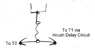 |
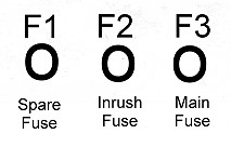
| Fuse Holders: A 6 Ampere slow-blow fuse is used for the main fuse at F3. A 1 Ampere fuse is used at F2 to protect the current inrush circuit. F1 is used to store a spare 6 Ampere main fuse. |
 |
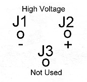
| High Voltage Output Connectors: The high voltage connectors and connecting cable must be able to safely withstand the full output of the plate supply, which can exceed 2500 volts. The only connectors that can safely withstand this voltage are made by the James Millen Co. and are known as "Safety Terminals" type 37001. RG59 coaxial cable is used to make the connection to the 813 amplifier. This type of connector is also used on the amplifier itself. J3 was originally for the screen voltage output, but it was decided to run the screen output to connector P1 instead, so J3 is not used. |
 |
| Screen and Bias Output
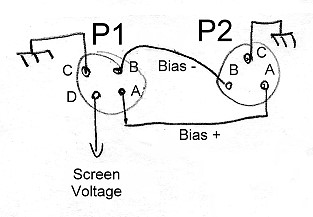
Connectors: Screen and bias output connectors P1 and P2 are also Amphenol Type MS receptacle connectors. As mentioned before, these connectors were relatively expensive, but could be obtained surplus at a reasonable price . Either connector can be used, though screen output is only available at P1. In practice, P2 is used, since the 813 amplifier uses the 813 as a triode and does not use separate voltage on the screen grid. |
 |
 Back to Dr. Greg Latta's
Electrical Engineering and Amateur Radio Pages
Back to Dr. Greg Latta's
Electrical Engineering and Amateur Radio Pages
 If you have any questions or
comments, you can send E-Mail to Dr. Greg Latta at
glatta@frostburg.edu
If you have any questions or
comments, you can send E-Mail to Dr. Greg Latta at
glatta@frostburg.edu