| 6146 Amplifier - Main Page and Exterior Photos | Plate and 10m Tank Coil Construction Details |
| Interior Photos of the Finished Amplifier | Construction of Input Coils L1 and L2 |
| Amplifier Schematic Diagrams and Circuit Descriptions | High Voltage Cage Construction |
| Power Supply Schematic Diagrams and Circuit Descriptions | 6146B Beam Power Tube and Data Sheets |
| Construction Photos | Typical Operating Conditions |
| Power Supply Circuits: |
| Power Transformer and Rectifier |
| Plate Power Supply Filter |
| Screen Power Supply Rectifier |
| Screen Power Supply Filter |
| Screen Voltage Regulator Circuit |
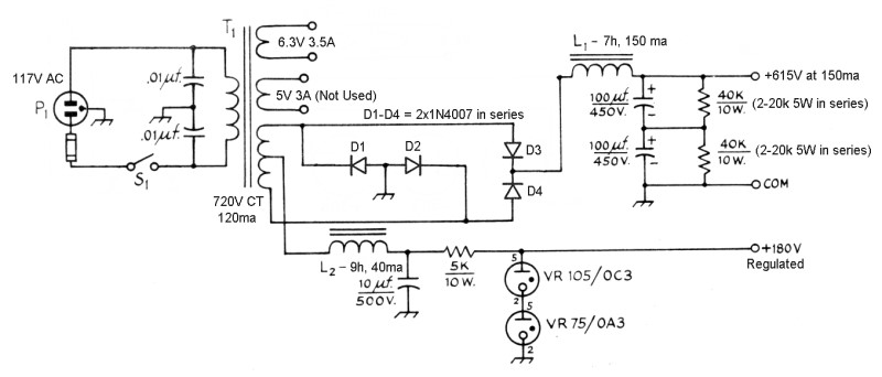
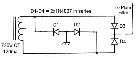
| Power Transformer and
Rectifier: The power transformer has three secondaries: 720V at 120mA center-tapped for the plate and screen supplies, 6.3V at 3.5A for the tube filament and bias power supply, and 5V at 3A (not used). Since the 5V secondary is not used, a little more current than 120mA can safely be drawn from the high voltage secondary. The high voltage secondary feeds a conventional full wave bridge rectifier to convert the AC to unfiltered DC, which is then fed to the plate power supply filter. Since the the PIV rating of one diode is not enough, two must be used in series, so the four diodes D1 through D4 are actually two 1N4007 diodes in series. For the purposes of the plate supply, the transformer center tap is not used. However, the center tap is used for the screen supply. |
 |
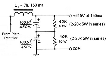
| Plate Power Supply Filter: The output from the plate rectifier is direct current (DC) but with a large alternating current (AC) component superimposed. The output from the rectifier in fed to a choke input filter. The filter choke allows the DC component to flow through, while offering a very high impedance to the AC component. The filter capacitors are essentially an open circuit to the DC, but they effectively short circuit the AC component to ground. The result is that little of the AC component reaches the output. Since the capacitors have a maximum rating of 450V, two are used in series to form a 900V 50uf capacitor. Two 40k, 10W bleeder resistors in parallel with each of the capacitors serve several important functions: (a) They bleed off the charge on the filter capacitors when the unit is shut off, preventing the possibility of a dangerous electric shock that could occur even though the unit were turned off and unplugged. (b) They provide a minimum load on the power supply to prevent the output voltage from soaring during standby periods. (c) They equalizes the voltage across the filter capacitors. The plate supply was bench tested and provides a maximum output of 615V at 150mA. |
 |
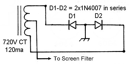
| Screen Power Supply
Rectifier: The power supply in the 6146B transmitter is a design commonly called an "Economy Supply". This design makes use of the power transformer and rectifiers in a very clever manner. All four diodes are used to form a full wave bridge rectifier for the plate supply, but for the screen supply, only diodes D1 and D2 are used. These two diodes, along with the transformer center tap, form a conventional full wave center tapped rectifier. The output of this rectifier is half that of the plate supply. This then feeds the screen filter. |
 |
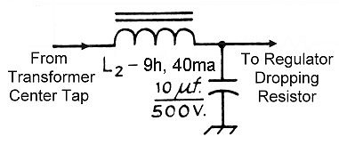
| Screen Power Supply Filter:
The output from the screen rectifier is then fed to the screen filter, which is a choke input filter which functions exactly the same as the plate supply filter. The screen filter then feeds the screen regulator. |
 |
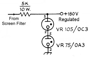
| Screen Voltage Regulator
Circuit: The output of the screen filter is fed to a voltage regulator that keeps the voltage at a constant 180V, unless the current exceeds the maximum value for the 6146B. The voltage then starts to fall off. Regulated screen voltage is very important in a linear amplifier, since the tube operation is sensitive to variations in screen voltage. If the screen voltage varies with the signal, the tube will not operate linearly, and distortion of the signal results. Gaseous regulator tubes such as the 0C3 and OA3 have the property that as long as the current through them is between about 4mA and 30mA the voltage across the tube is constant. When such tubes are placed in series they act as a single tube that operates at the sum of their voltages. The value of the dropping resistor (5k in this case) is quite critical. The resistor must be selected so that the regulator tubes remain lit if the screen current is 15mA or less, but extinquish if the current goes over about 17mA (the maximum permissible value for the 6146B at a screen voltage of 180V). If the resistor value is too low, it is possible to damage the tube by overheating the screen, as can easily happen during amplifier tune-up. When the proper value is selected, the screen voltage stays constant during normal operation, but drops if too much current is drawn, limiting the screen input to a safe value. (Before I understood this, I ruined two 6146Bs. One was, fortunately, and old tube, but one was brand new. What a way to throw away $$$!! It breaks the heart...) |
 |
 Back to Dr. Greg Latta's
Electrical Engineering and Amateur Radio Pages
Back to Dr. Greg Latta's
Electrical Engineering and Amateur Radio Pages
 If you have any questions or
comments, you can send E-Mail to Dr. Greg Latta at
glatta@frostburg.edu
If you have any questions or
comments, you can send E-Mail to Dr. Greg Latta at
glatta@frostburg.edu
This page is under constant revision. Please check back often.