
The 6146 beam power tube and its various descendents (6146A, 6146B) was and still is one of the most popular transmitting tubes in amateur radio service. The tube was originally introduced by RCA in an ad in the January, 1952 issue of QST magazine:
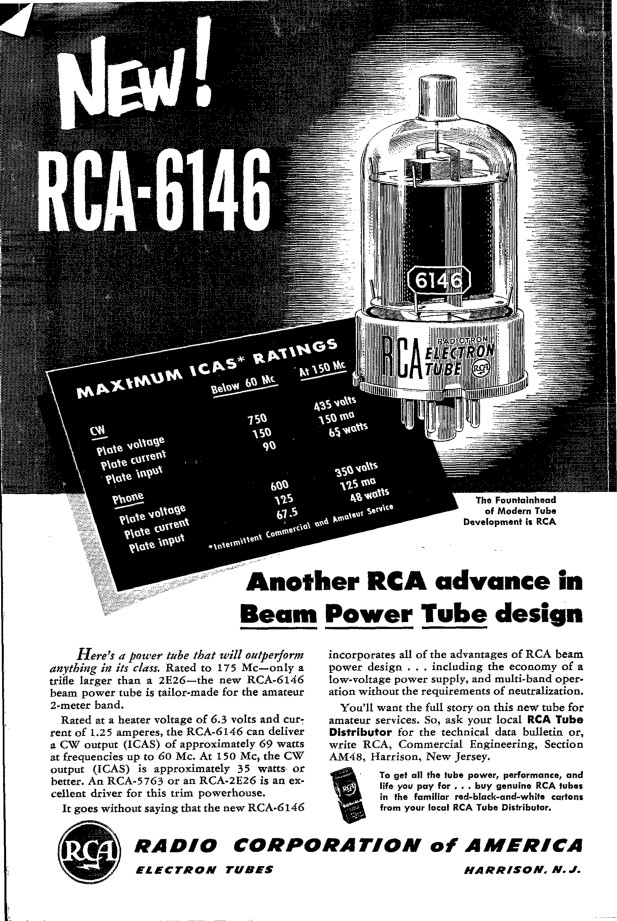
With an ICAS plate dissipation of 25 watts a single 6146 could produce a maximum output on CW of 69 watts while operating with a plate voltage of only 750 volts. This was remarkable compared to other tubes available at that time, which required higher plate voltages and/or higher driving power for the same output. As the 1950s progressed and SSB began to replace AM as the preferred mode for phone operation, the tube proved ideal in linear amplifier service, and a pair of 6146 tubes in parallel became a very popular combination in commercial and homebrew SSB amateur transmitters.
12 years later, in the January, 1964 edition of QST, RCA introduced the 6146B, a major revision of the 6146:

The 6146B featured a new plate design that allowed the ICAS plate dissipation rating to be increased from 25 watts to 35 watts, a whopping 40%. As a result tube input could be increased by 33 1/3%! By simply plugging in a 6146B in place of the original 6146, and raising the screen voltage from 160 volts to 200 volts, (an operation that wasn't usually very difficult) a transmitter that originally had an output of 69 watts would now have an output of 85 watts. Without circuit changes, the newer tube was simply more rugged, could take more abuse (as often occurred during tune up), and simply lasted much longer than the 6146. In SSB service switching a pair of 6146s to 6146Bs resulted in an even larger improvement. The result was that many of the commercial tube transmitters from 1964 on featured a pair of 6146Bs in the output stage. In fact, one could argue that a pair of 6146Bs was the defacto standard in amateur transmitters until solid state gear began to replace tube gear in the 1970s and 1980s.
Despite what the above advertisement implies, the 6146B is not always a drop in replacement for the 6146/6146A. In some cases the slight difference between the interelectrode capacitances in the 6146/6146A and 6146B causes problems with neutralization. Some transmitters originally designed for the 6146/6146A do not have sufficient range on their neutralizing capacitors to be properly neutralized when using the 6146B. These transmitters must have their neutralizing circuits modified to obtain proper neutralization.
There is also a 6146W, which is a military version of the 6146/6146A or 6146B. The trouble is that some 6146Ws are 6146/6146As, and some are 6146Bs! If you are going to use a 6146W in place of a 6146B, be sure the 6146W your are using is rated for service as a 6146B. If you are going to use a 6146W to replace a 6146/6146A, then be aware that it might be a 6146B and you might have the neutralization problem mentioned in the previous paragraph.
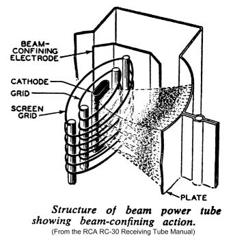
The 6146 series of tubes followed on the heels heels of the famous 6L6 beam power tube, which was the first power tube to use the electron beam principle.
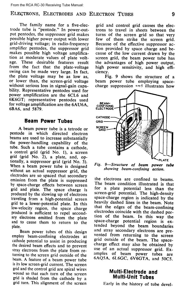
The 6L6 was released in 1936 and was first announced on page 50 of the May, 1936 issue of QST magazine. The 6L6 revolutionized power tube design by forming the electrons into beams and using aligned control and screen grids to limit grid and screen currents. Forming the electrons into beams increased the space charge near the plate, which then repelled secondary electrons back to the plate, eliminating the need for a surpressor grid. See the diagram below. Other beam tubes eventually followed, including the 6146, 6146B, 6146W, 2E26, 5763, 813, 6V6, and others.
| Page: | Contents: |
| 1 | Introduction and General Data |
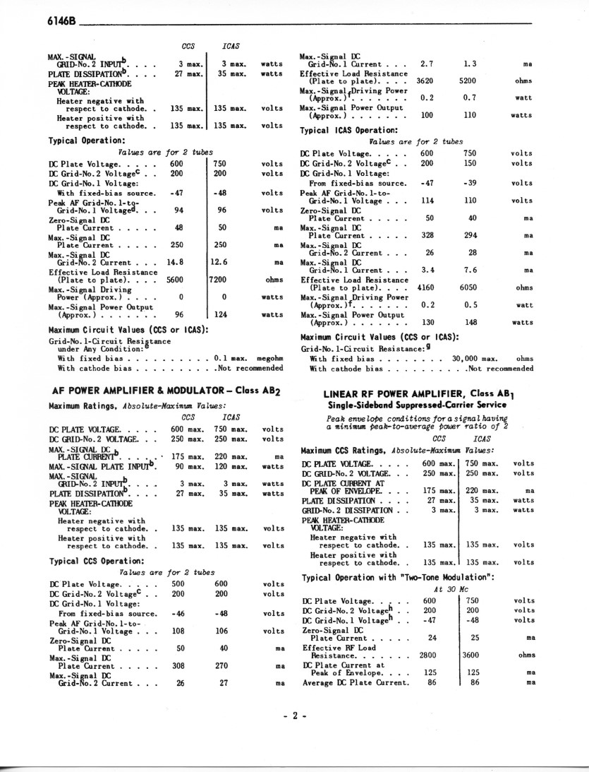
| 2 | Typical Operation 1 (Includes Linear RF Power Amplifier Class AB1) |
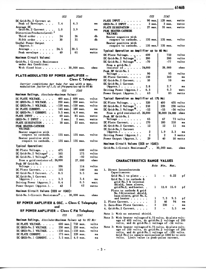
| 3 | Typical Operation 2 (Includes RF Power Amplifier Class C) |
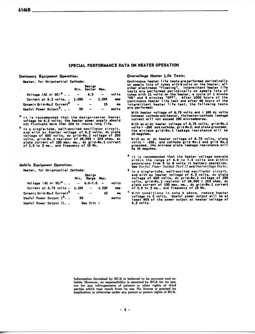
| 4 | Special Performance Data on Heater Operation |
| 5 | Maximum Ratings |
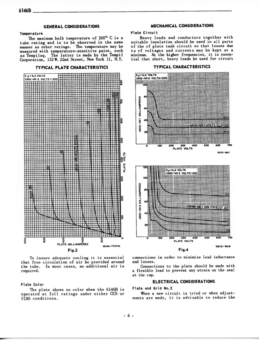
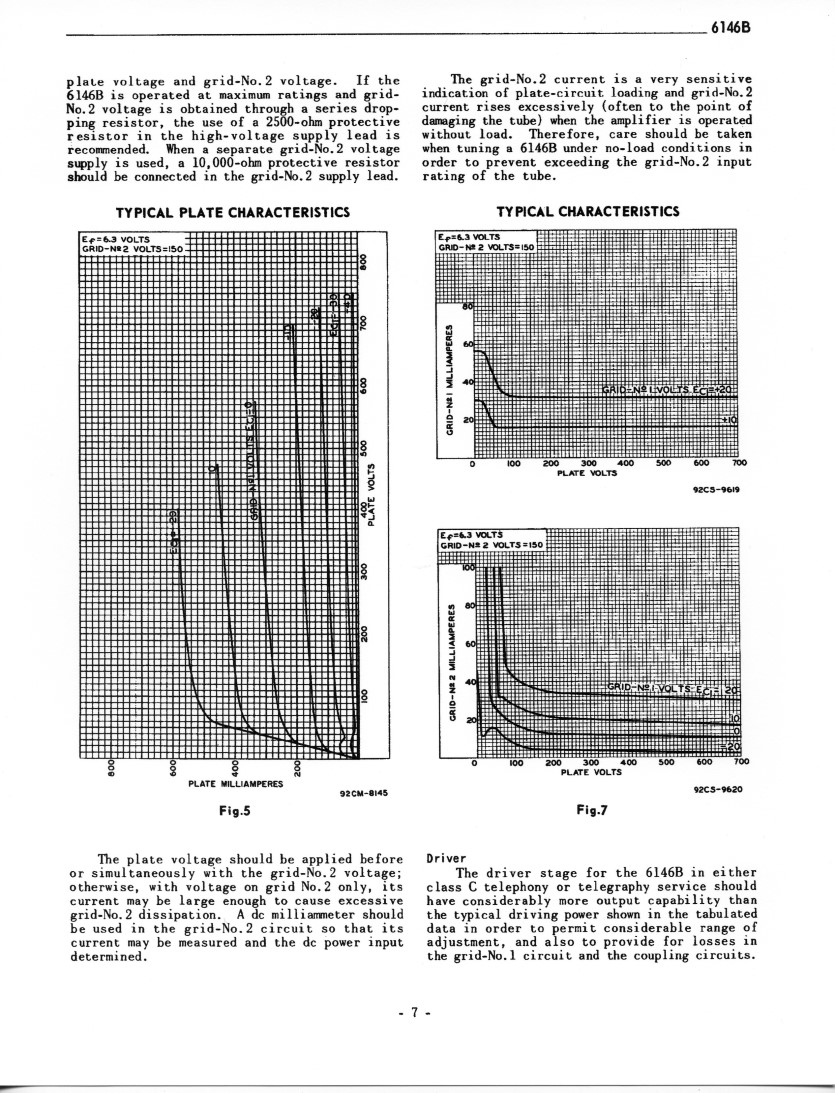
| 6 | General and Mechanical Considerations and Characteristic Curves |
| 7 | More Characteristic Curves |
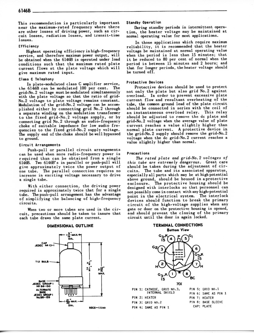
| 8 | Miscellaneous Information, Tube Outline, and Basing Diagram |
| Complete 6146B data sheets in PDF format |
| Complete 6146 data sheets in PDF format |
 Back to Dr. Greg Latta's
Electrical Engineering and Amateur Radio Pages
Back to Dr. Greg Latta's
Electrical Engineering and Amateur Radio Pages
 If you have any questions or
comments, you can send E-Mail to Dr. Greg Latta at
glatta@frostburg.edu
If you have any questions or
comments, you can send E-Mail to Dr. Greg Latta at
glatta@frostburg.edu