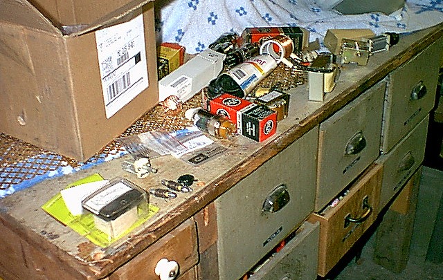
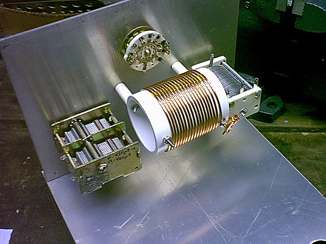
| A Workbench Full Of Parts: All projects must start somewhere, and this one started as a pile of parts on my workbench. At this stage I had just finished making the tank coil and had finally rounded up all of the other parts. Across the front of the workbench, from left to right, can be seen the meter (yellow), a couple of RF chokes, the 6146B and its plate cap, the bias power transformer (brown), plate power supply choke (white), loading capacitor, and plate tuning capacitor, with a black knob on its shaft. |
 Click on the image for a larger view. |
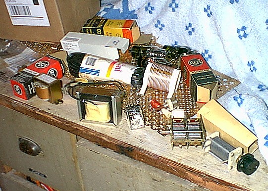
| A Workbench Full Of Parts From Another Angle: This is another view of the pile of parts that would eventually become the amplifier. From right to left on the front are the bias power supply transformer (brown), plate power supply choke (white), relay, loading capacitor, and plate tuning capacitor (with black knob). Further back are the line cord (black), plate tank coil (white), and the regulator tubes. Underneath the entire mess is the gold anodized aluminum that would eventually become the high voltage cage. |
 Click on the image for a larger view. |
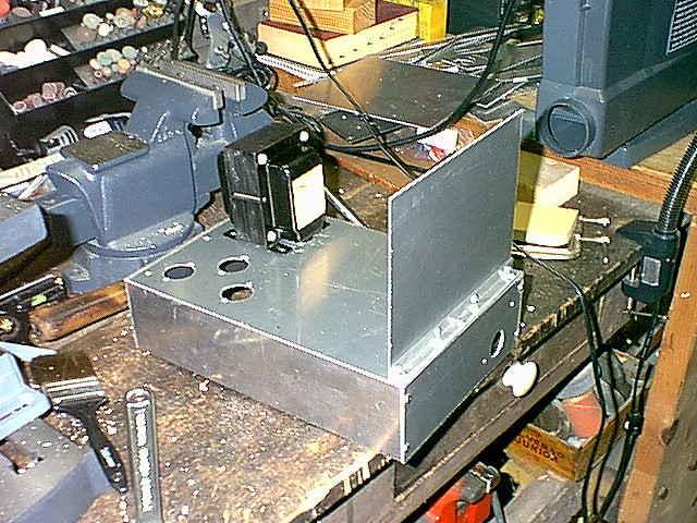
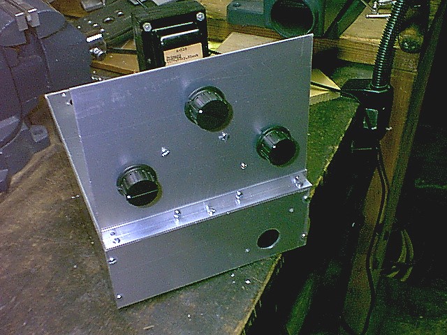
| Chassis With Power Transformer And Front Panel: The first part of the construction process was to use my machine shop to make a chassis. Chassis sides were made out of 1/4" aluminum plate, and the front panel and chassis top were made out of 1/16" sheet aluminum. In this photo, the front panel has temporarily been fitted to the chassis. The power transformer has been mounted and holes have been punched for the regulator tube sockets and the front panel meter. |
 Click on the image for a larger view. |
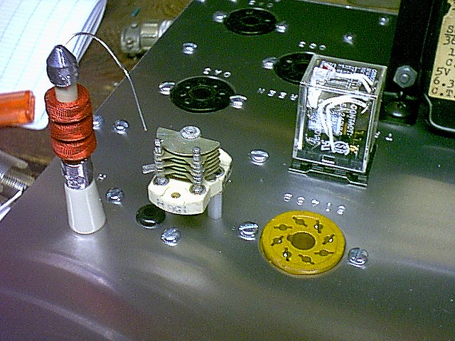
| Tank Circuit And Band Switch Mounted On Front Panel:
After the front panel and chassis are constructed, it is time to mount parts. In this photo the output loading capacitor (left), plate tank coil (center), and plate tuning capacitor (right) have been mounted to the back side of the front panel. The band switch (top center) has also been mounted. |
 Click on the image for a larger view. |
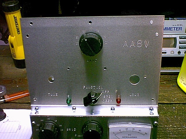
| Front Panel With Knobs: To see how the front panel will look, knobs have been placed of the plate and loading capacitors and the bandswitch. Mounting holes have also been made at the bottom of the chassis for the front panel meter. (The function switch and pilot lamps are yet to be mounted.) |
 Click on the image for a larger view. |
| Mounting The Pilot Lamps And Function Switch: After the plate loading and tuning capacitors were installed, they were temporarily removed so that the function switch and pilot lamps could be mounted. In this photo the function switch is visible at the bottom center of the front panel flanked by the the red and green pilot lamps. The neutralizing capacitor and plate RF choke are also visible at the extreme bottom of the photo. |
 Click on the image for a larger view. |
| Plate RF Choke, Neutralizing Capacitor And Relay: The plate RF choke (red), neutralizing capacitor, and relay are visible in this picture of the chassis top. You can also see that the chassis has been stamped with the tube numbers, and the tube sockets have been installed. The power transformer is just visible in the back on the right. |
Click on the image for a larger view. |
| Front Panel Without Plate and Load Controls: Sometimes during construction it is necessary to remove certain components to install others. In this photo the plate tuning and loading capacitors have been removed to facilitate the wiring of the mode switch, band switch, and pilot lamps. The green pilot lamp lights when the transmitter is turned on, the red lights whenever the amplifier is in operate mode. You can also see at the bottom of the photo that the grid band switch, grid tuning capacitor, and meter have been installed. |
 Click on the image for a larger view. |
| Most Of The Components Are Mounted On The Chassis Top:
In this picture of the underside of the chassis top, most of the components and tube sockets have been mounted, but only the wiring to the bias power supply filter (blue capacitor at upper left) and screen power supply filter (white power resistor at top left) have been completed. The plate power supply choke and bias power supply transformer can be seen at the lower right, and the screen power supply choke is visible at top center. |
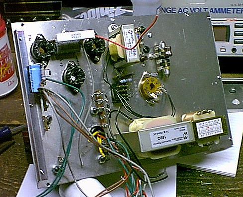 Click on the image for a larger view. |
| Power Supply Wiring Finished: In this picture, taken from exactly the same angle as the one above, the wiring to all three power supplies (plate, screen, and bias) has been completed and the power supplies are ready for testing. The plate supply filter capacitors are the large blue ones at the bottom left of the picture, and the plate bleeder resistors are the four white power resistors in between the capacitors. These bleeder resistors were eventually moved to a position above the capacitors to keep the heat they produced away from the capacitors. The two gray wires coming out at the bottom of the picture are primary leads to the power transformer. |
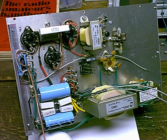 Click on the image for a larger view. |
| Power Supply Test: After wiring the power supply, the transformer primary was connected to 117V AC and the power supply checked out. Everything worked fine. In this picture the glow of the voltage regulator tubes can be seen. Two of the tubes (0A3) glow yellow and the other (0C3, in the middle) glows purple. As current is drawn from the screen and bias supplies, the tubes glow dimmer, and thus they pulsate with keying or with speech on a SSB signal. |
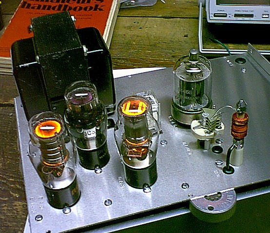 Click on the image for a larger view. |
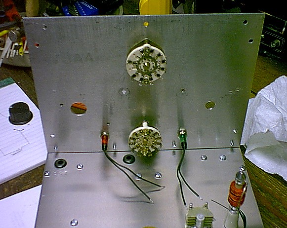
| Bottom Of Front Panel Inside: After the power supply was wired and tested, work began on the rest of the amplifier. In this picture the input band switch, mode switch, grid tuning capacitor, and meter have been mounted on the front panel, but have not been wired into the circuit. Compare this photo to those on the interior photos page to see how the amplifier looks when the wiring is completed. |
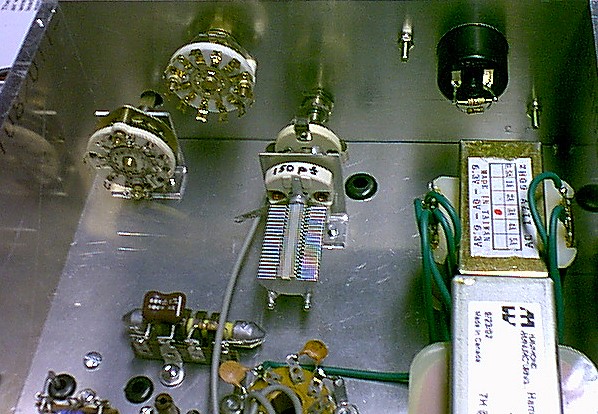 Click on the image for a larger view. |
 Back to Dr. Greg Latta's
Electrical Engineering and Amateur Radio Pages
Back to Dr. Greg Latta's
Electrical Engineering and Amateur Radio Pages
 If you have any questions or
comments, you can send E-Mail to Dr. Greg Latta at
glatta@frostburg.edu
If you have any questions or
comments, you can send E-Mail to Dr. Greg Latta at
glatta@frostburg.edu
This page is under constant revision. Please check back often.